Click any image to enlarge
Cooking inside our camper is something we plan to do only when we have to. Our preference is to cook outside whenever possible, therefore there is a requirement for an external barbecue and/or hotplate.
The logical location for an external barbecue is on the passenger’s side of the vehicle, so in our truck that means the only feasible position to house the barbecue is behind the rear wheel, as this is the only space on that side which is big enough. This is not an ideal location however, as it is right at the end of the truck. Although this area would be covered by an awning, the barbecue would be right at the end of the awning and potentially subject to wind and rain. As I said, not ideal.
Given that I did not really want to have the cooking facilities right at the back of the truck, this ruled out using a commercial pull-out slide.
Therefore, it was necessary for me to design and manufacture my own slide-out system for our barbecue.
Initially I thought that this would be a fairly straight forward exercise, but it definitely did not work out that way. When I look back on the completed unit, the design I ended up with seems quite straight forward, but it took a while to get to that point.
My criteria was to design a frame system that could position our barbecue in front of the passenger’s side rear wheel.
A slide-out mechanism was required to position the frame that holds the barbecue far enough away from the camper body. The frame that supports the barbecue needs to pivot 180°, so that it can go from the stored position then swing around to be in front of the rear wheel.
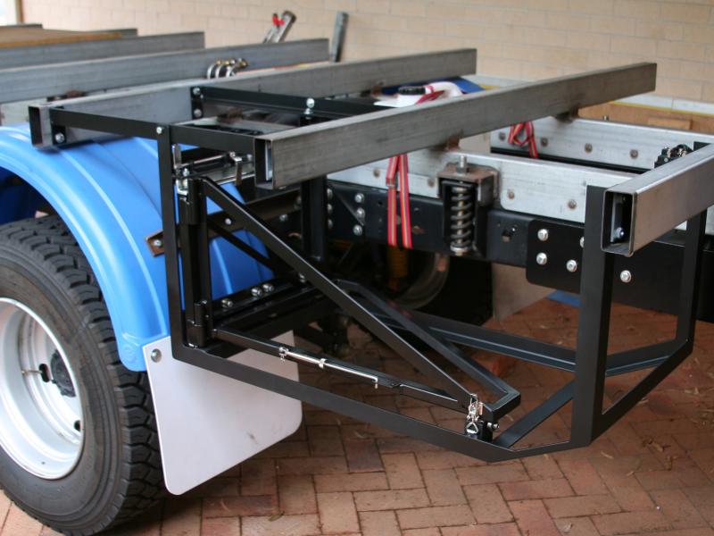
The slide system that I decided to utilise is similar to many used in heavy duty draw systems. Basically, it consists of guide rails that are supported by sealed roller bearings. The greatest technical challenge was to build a slide system strong enough to support the weight of the barbecue when being used. The problem was that it would not be possible to incorporate any lateral braces, due to the fact that these would interfere with the rotation of the barbecue support frame. To that end, I had to go with heavier section steel to obtain the strength required.
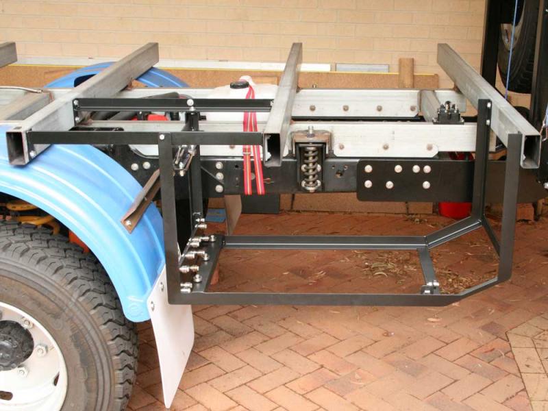
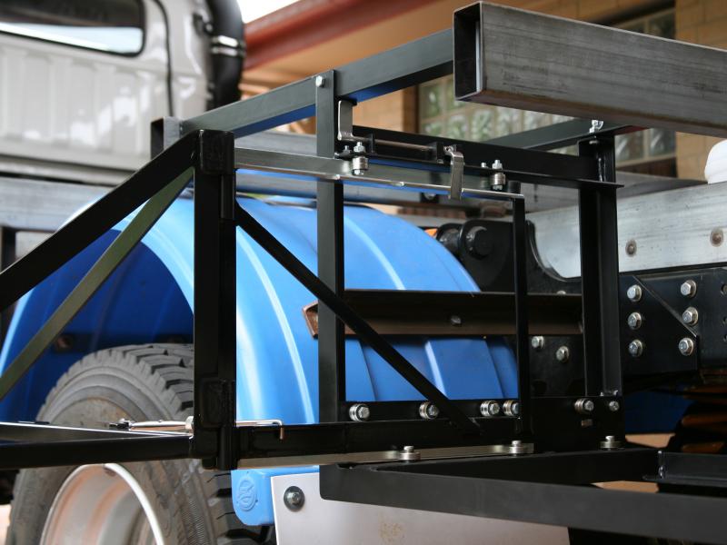
The frame system I designed is made up of three distinct parts; the main frame, the slide out mechanism and the frame that will ultimately hold the barbecue. The slide out mechanism utilises two rails, one upper and one lower, and incorporates a hinge for the barbecue support frame.
It probably would have been more logical to start by building the main frame, but I didn’t do this, I started with the slide out mechanism
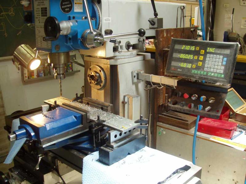
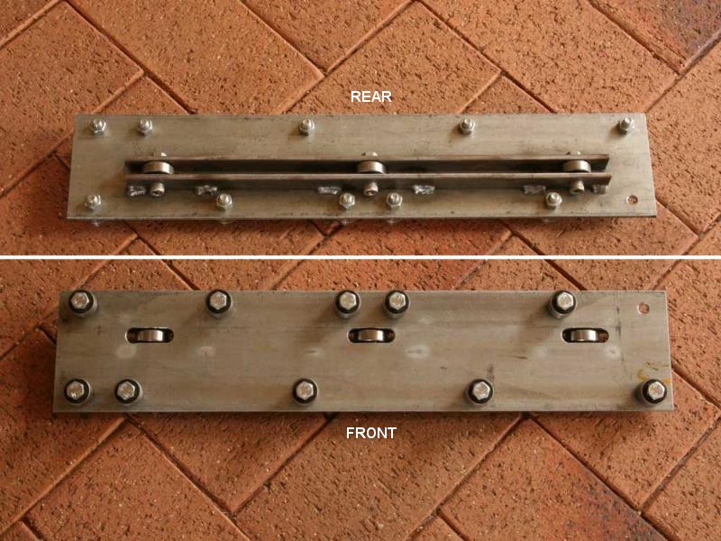
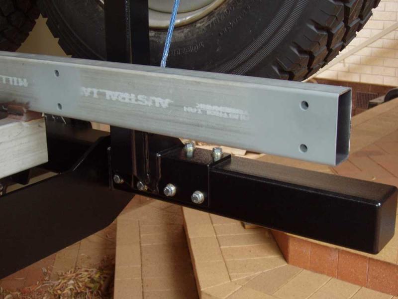
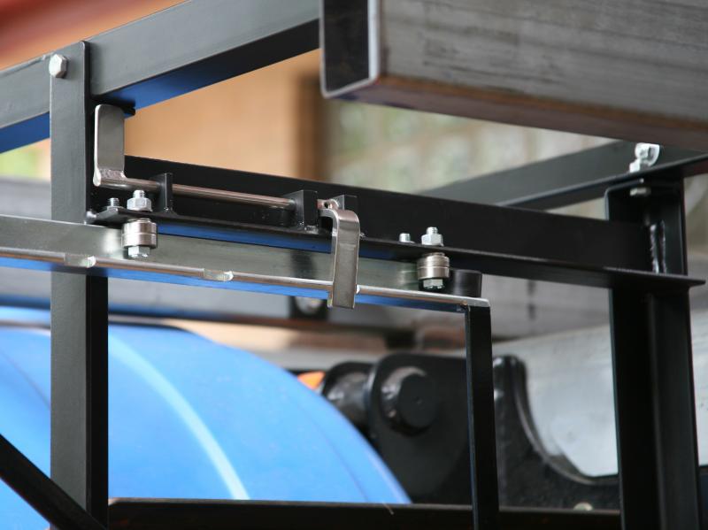
Using a digitally controlled milling machine, holes and slots for the bearings were machined into a piece of 100mm x 5mm flat plate. I could of simply marked out the holes and drilled them on a drill press, but I am basically lazy, so I did it this way because it was easier. Two lengths of 20mm x 5mm flat bar were welded to the rear of this plate to add additional strength and these were also used to mount the lateral support bearings. This plate is the main part of the slide mechanism and takes all of the vertical loads.
The lower section of the slide-out rail is made from 50mm x 25mm x 2.5mm RHS and the upper rail is made from 30mm x 6mm angle. Lateral support at the bottom comprises of three bearings on the plate described above and another three opposing bearings which are mounted on a piece of 40mm angle, which is welded to the main frame. At the top, bearings are located on either side of the angle. The strength of the top rail, along with the upper and lower support bearings provide decent lateral support.
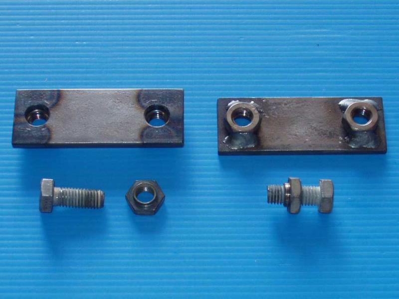
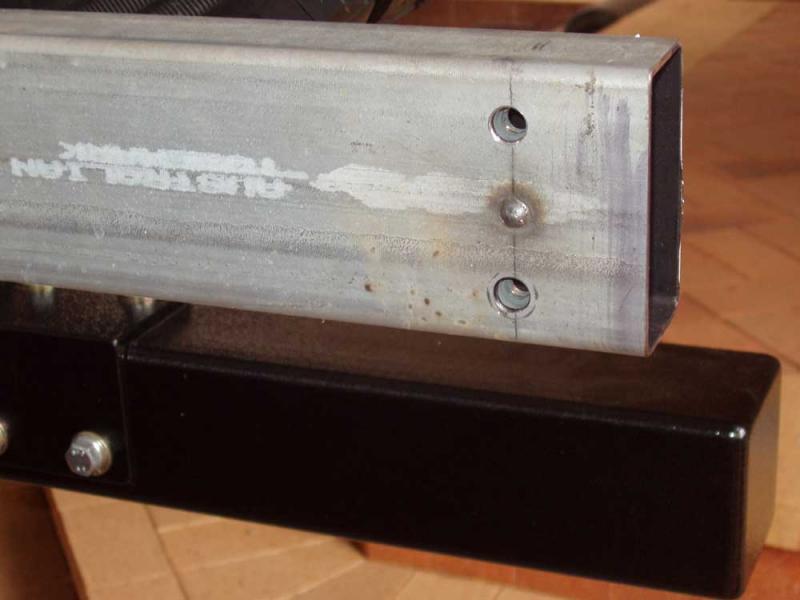
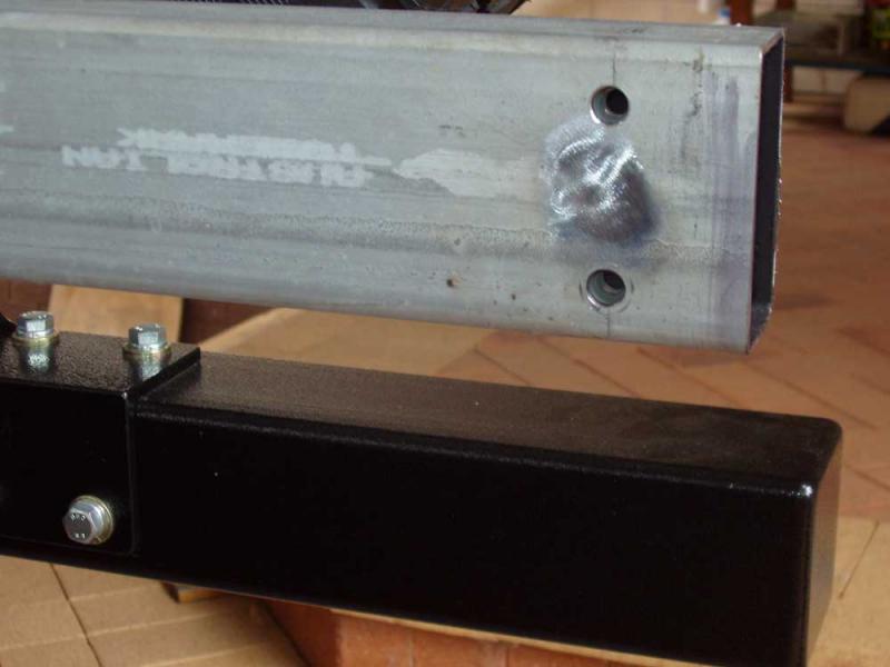
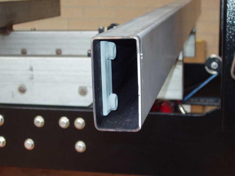
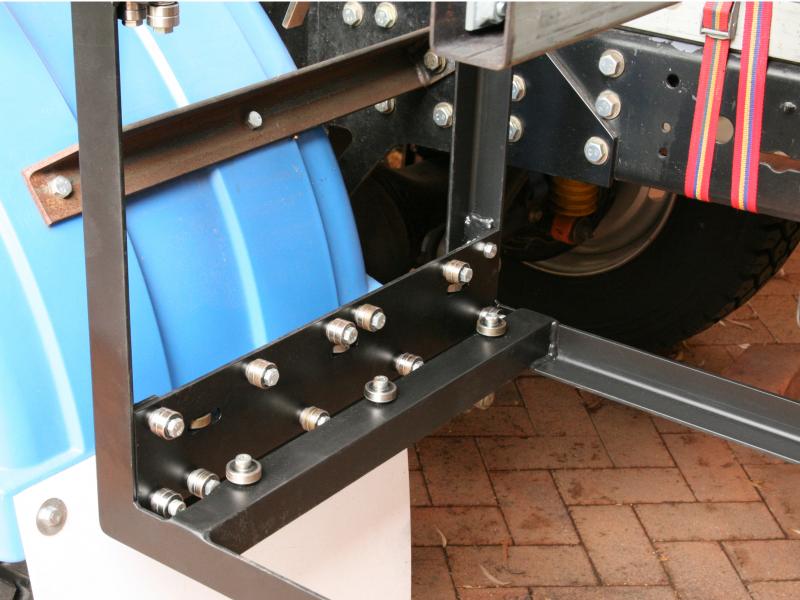
The frame that houses the slide out mechanism is made from 40mm x 5mm angle. This is probably a little heavier than really necessary, but it avoids having to use additional bracing. To mount the front legs of the frame I made two horizontal brackets, also from 40mm x 5mm angle. These brackets attach to the subframe rails and the barbecue frame attaches to them. The rear legs of the frame are bolted directly to the end subframe rail. All of the fixation points on the subframe rails are done in a similar manor to how I have done it previously; they utilise a captive nut system that allows me to bolt to the RHS subframe rails, as opposed to welding.
Another thing that I needed to design was a latching system for the slide-out rail. In my experience, it often takes considerably longer to make something “simple”, and that was definitely the case with this latching system. The final solution was to use a spring loaded lever that locked into notches in the top slide rail. All of the components for the latching mechanism are made from stainless steel, including the spring.
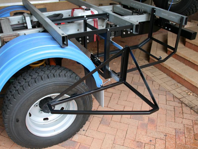
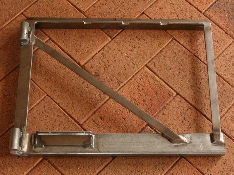
The base of the frame that will house the barbecue is made from 25mm x 2.5mm SHS. This frame has two diagonal support braces that join at the top pivot hinge. The hinges on this frame are standard gate hinges, which allows the frame to be removed from the slide rail. This gives us the option of detaching the barbecue from the truck and locating it somewhere else, like on a table. I do not know if we will ever want to do this, but it was simple to add this option, so I did.
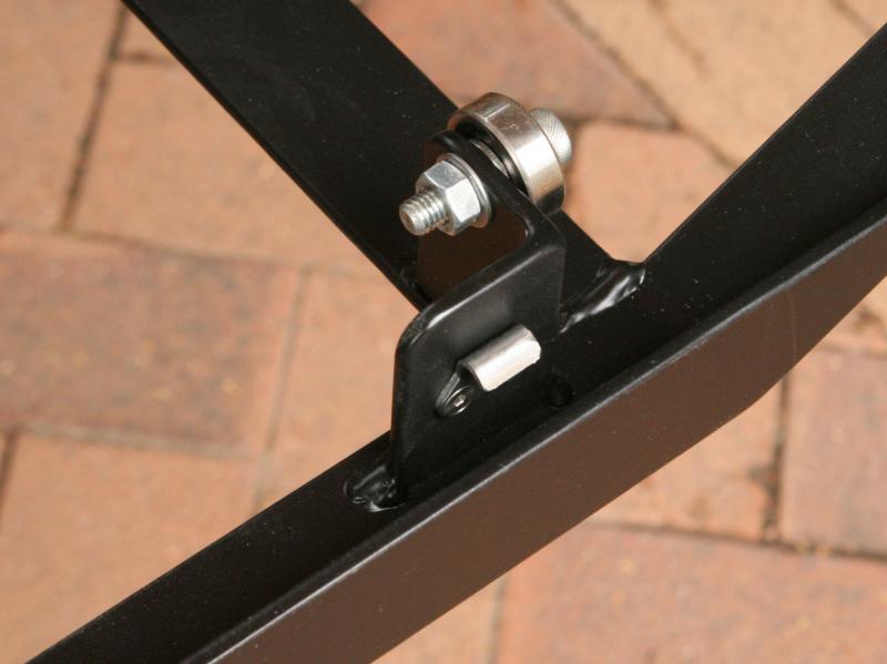
When the barbecue support frame is in the stored position it is locked into place with an over centre latch. I also included a support bearing, so that the load is removed from the hinges and slide rail when not in use.
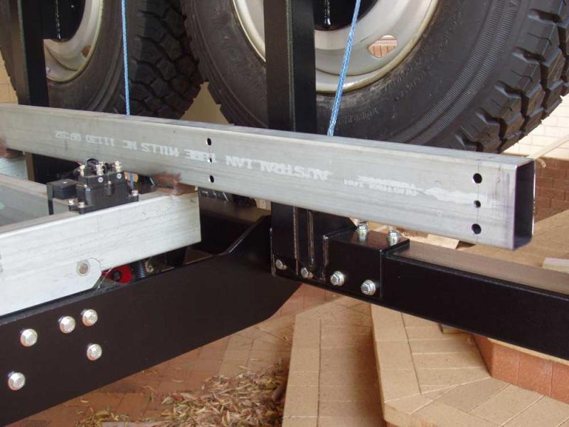
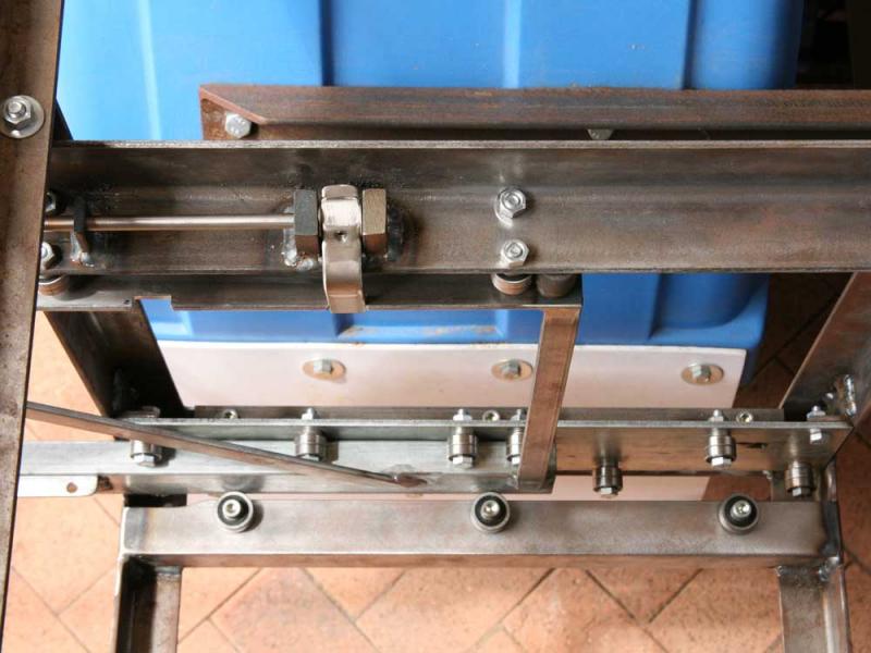
To use the barbecue, the frame is first unlatched and when the slide latching lever is pushed, the slide rail, along with the barbecue support frame, can be slid forward. The barbecue support frame is then rotated 180° and positioned in front of the rear wheel. With the barbecue in this position it is more than a metre from the rear of the truck, which is a much better working position for it.
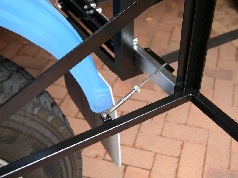
To secure the barbecue support frame in this position I used a modified marine grade turnbuckle. This is attached to the support frame at one end and it hooks into the slide out rail at the other end.
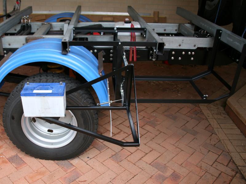
A load test was carried out to ensure that the barbecue support frame and slide-out rail could support the weight of a barbecue unit.
A 30Kg battery was placed at the furthest point from the hinges and this resulted in only a 3mm deflection of the frame. I estimate that this design could easily support 50Kg, not that I will ever have anything near that weight on the frame.
When the camper body has been built and attached to the subframe, cladding will be attached to the barbecue main frame, making this a fully sealed box. A water tap will also be added in this area.
As would be obvious from looking at the images I have shown here, at this point in time I do not actually have a barbecue.
We have not yet decided on what type of barbecue to get, that’s why there isn’t one. The important thing at this time was to build the housing for the barbecue, which I have now done.