Click any image to enlarge
If I could have found some commercial steps that were suitable for my setup I probably would have used those. Alas, nothing on the market looked like it would work for me, so I was forced to make my own camper entry steps.
Making a set of steps might sound like a fairly simple task, but I have to say, this part of the project has been the most frustrating so far.
I started working on a design for these steps very shortly after I had finished building the subframe, which was many, many months ago.
Many hours have been spent making mock-ups from cardboard (over a dozen) but none of them worked exactly as I wanted. With every failed attempt at creating a working design I got more and more frustrated, thinking that I would never solve this entry step problem.
I had nearly given up, resigning myself to the thought that I would have to use some removable steps, which I really did not want to do.
Here are some of the criteria/issues I needed to address:
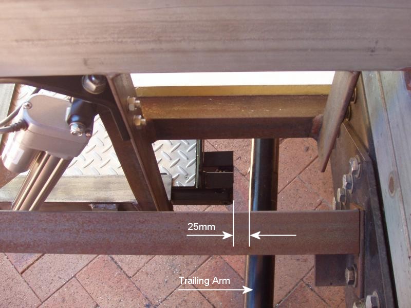
- There is only 475mm between the front of the steps frame and the trailing arms of the rear suspension, making space a major issue.
- Ideally, the steps would not reduce the ground clearance significantly when retracted.
- The steps should be automated. This was not mandatory, but it was highly desirable.
- The steps should have a tread length as long as possible (at least 230mm – 9 inches) making them safer to use.

Finally, after making yet another cardboard mock-up, I came up with a design that I thought might actually work. I tested the mock-up on the truck and confirmed that it could be viable, so I started drawing it up in AutoCAD. A few changes to the design needed to be made to allow for material differences, but everything still looked good after doing this, so I decided to go ahead and start manufacturing the steps.
It had taken nearly eighteen months to get to this point, so I was very eager to get started…
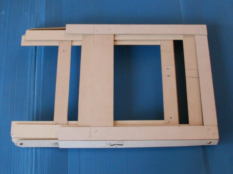
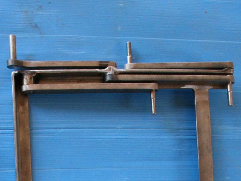
My design allows for the steps to retract into themselves, which means that the fully retracted height is only about 50mm. This was ideal, but it definitely created some technical challenges. I know why there are no commercial steps with a similar design to mine… it’s too complicated!
The biggest issue with this design is that it requires very tight tolerances in order for the steps to move freely. Being out by as little as 1mm, or less in some cases, will result in the linkages binding when in the fully retracted position. I could have marked out all of the holes manually, but having access to a digitally controlled milling machine and using AutoCAD definitely made this job significantly easier.
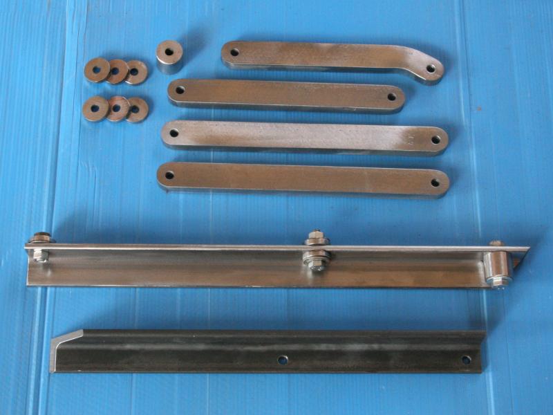
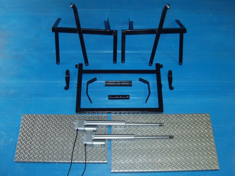
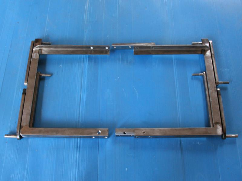
The primary materials that I used included 25mm x 12mm flat bar, for the linkages and 30mm x 6mm angle for the steps.
This is quite heavy material, I know, but I felt that this was necessary for the design. I still believe that if I had used lighter/thinner material it may have bent when put under load, and obviously that would not have been desirable.
I also made up some spacers from 25mm bright bar stock. These are used to give the required clearance needed between the linkages. I had access to a surface grinder, so I used that to get all of the spacers exactly the same thickness.
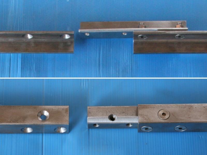
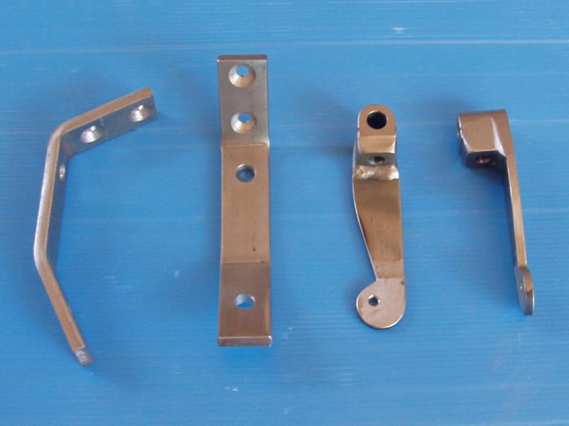
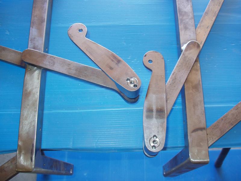
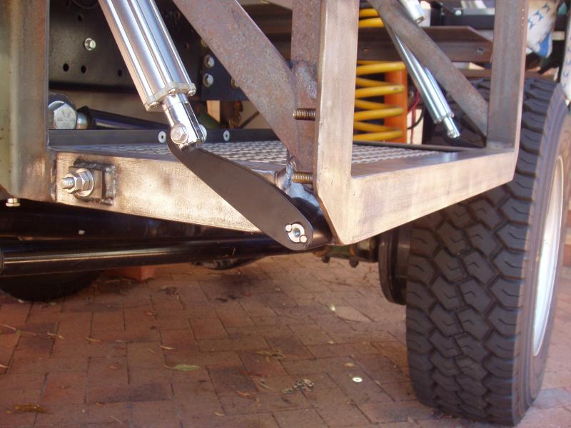
One of the main challenges was creating a strong centre linkage. That was mandatory, as the centre linkage is the one that drives the steps.
The problem is that the centre linkage cannot be one piece, it has to be two pieces. This is necessary for the steps to retract as designed.
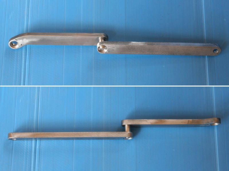
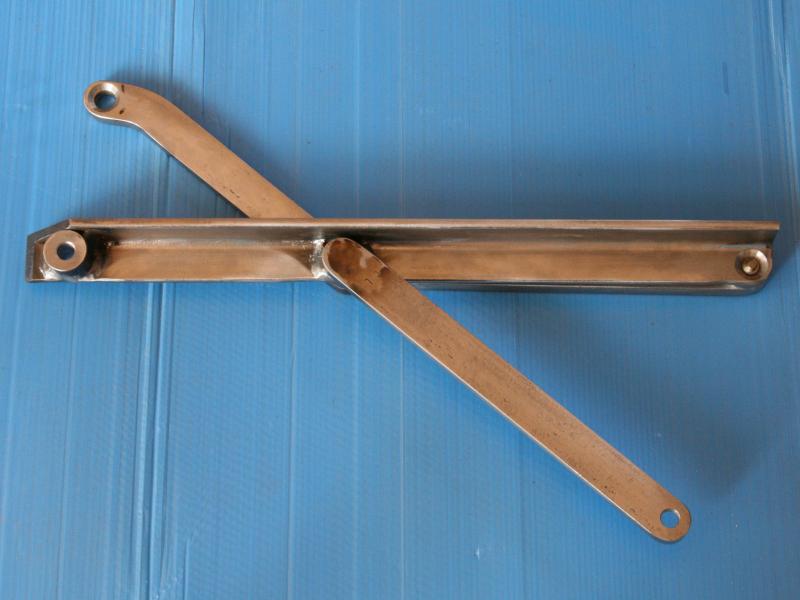
The centre linkage is made up of two separate arms which are joined by a 12.7mm stainless steel pivot pin. To stop any rotation of these arms on the pivot pin, the pivot pin was keyed then welded on both ends. The biggest problem with this approach is that the centre linkage is then permanently attached to the 30mm angle of the step. Numerous other methods for doing this joint were considered, but in the end I decided that this was the strongest option, so that’s what I went with.
Due to the minimal clearances between the linkages when the steps are retracted, all of the other linkages that attach directly to the top step were also welded. For the pivot pins on these linkages I used some M10 316 stainless steel flat head socket screws. The pivot holes in the linkages were countersunk, which allowed the socket screws to sit pretty flush, giving the necessary clearance. Finding stainless steel socket head screws that were not fully threaded required quite a bit of searching. Luckily, I found ten, which was just enough to do the job. Who knew finding the right bolts would be so hard?
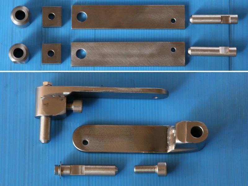
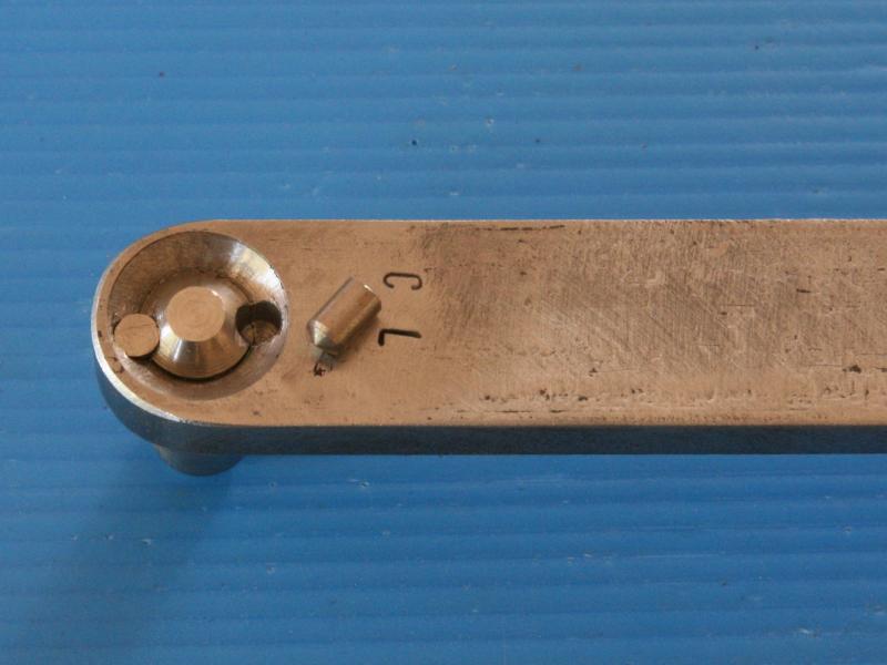
The drive pin that connects the centre linkage to the actuator arm is keyed and welded at one end, in the same way the centre pivot was done. There is a flat on the drive pin that allows positioning of the actuator arm at the correct angle, relevant to the centre linkage. A M10 stainless steel cap head screw secures the actuator arm to the drive pin. The screw done up onto the flat of the drive pin is not sufficient to withstand the torque that will exist when standing on the step, so the drive pin also has two removable 5mm round keys fitted. These keys are held in place with a M6 bolt and washer.
Just to be sure, Loctite will also be used on the keys, drive shaft and M10 bolt on final assembly of the steps.
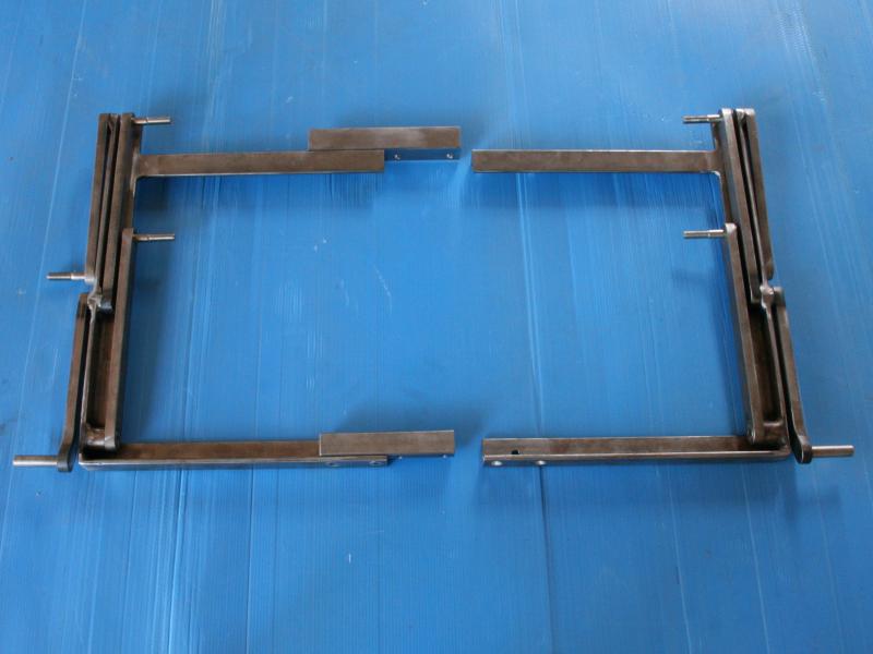
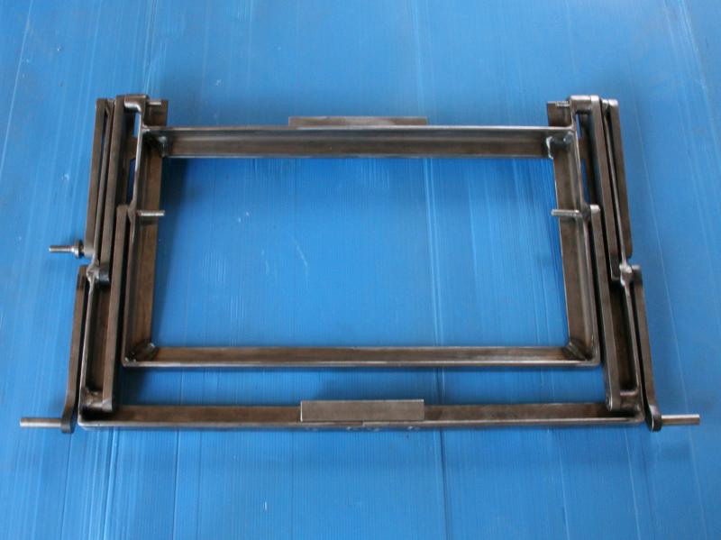
By welding the drive pins onto the centre linkages I created another problem; the steps could not be installed! The solution was to build the top step in two separate pieces, which I did. The greatest amount of load will exist on the front rail of the step so for this join a length of 25mm square bar was used. This is secured using six M8 stainless steel socket head screws. The rear rail is joined with another length of 30mm x 6mm angle.
The treads for the steps are made from 2mm stainless steel checker-plate and are attached by means of countersunk head M4 x 8mm stainless steel screws. There was no room for nuts under the 30mm angle of the steps, as these would have hit the linkages. To get around this issue, all 24 of the holes in the angle were tapped. If the checker-plate works out to be too slippery when wet I might consider changing this for expanded mesh down the track, or I could paint them with some anti slip solution. Will test them out first before making any changes.
One of my design criteria was that the steps be automated. The reality is that I am basically lazy, so pushing a button to extend/retract the steps is preferable over having removable steps that have to be put in place and removed manually every time you want to use the camper.
Over the many months it took to get to this point I had looked at numerous automation options, taking particular note of how commercially available steps worked and also some of the custom made steps I had seen on a few of the 4×4 tour buses.
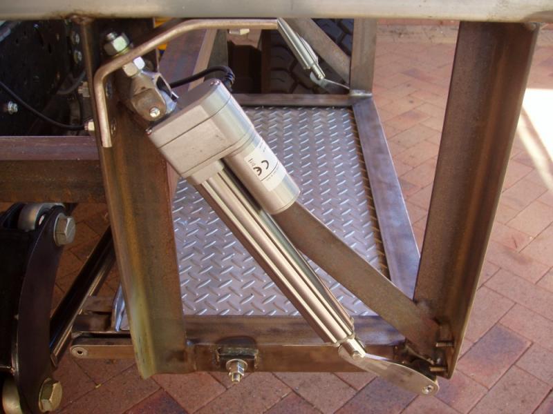
I do not have hydraulics in the truck, so I ruled that out early in the piece, as this would have added even more cost. Pneumatics and right angle drive motors were considered, but I could not find any solution using these that would really work with my design restrictions. In the end I chose to use 12 volt linear actuators. Because linear actuators utilise a nut and screw mechanism they effectively “lock” when the motor stops. This design makes them safer and also means that the static load capacity of the actuator is much higher than the rated dynamic load.
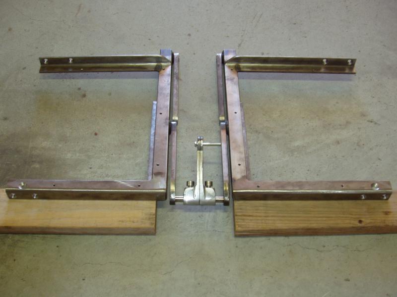
My preference would have been to use a single actuator that pushed at the centre of one of the steps. Unfortunately, it was not technically possible to get an actuator which had the necessary stroke length into the available space. The only viable option was to use two smaller actuators; one on either side of the steps. Using two actuators creates other potential issues however, the main one being dealing with what happens if one of the actuators fails. There needs to be some “smarts” in the electronics that powers the two actuators so that if this happens the system stops immediately, averting the potential of driving just one side and ripping the steps apart. Luckily, you can get these actuators with feedback devices installed (potentiometers or hall sensors), so knowing what each actuator is doing is not that difficult. Another issue is keeping the two actuators in sync with each other. My design will accommodate a small variation in actuator speed, so this isn’t a real problem.
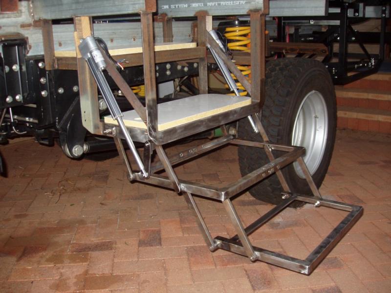
I purchased two 12 volt 1200 Newton (120Kg) linear actuators directly from a factory in China as a “proof of concept”.
As much as the steps seemed to function well when extended/retracted manually, I was still not overly confident that they would when using actuators, given the mechanical disadvantages in the linkages. When I received the actuators the first thing I did was a simple function test to see if they could withstand the load when I stood on the bottom step. This involved connecting the actuator rod ends to the actuator arms, bracing the other end in the step frame and standing on the step.

I was very happy to find that the actuators dealt with me bouncing up and down on the steps, but I still had no idea how much force was being applied to the actuators. To figure this out I could have used some complicated vector mathematics, but I chose to use a much simpler real world solution. I jerry rigged a setup where I could use our bathroom scales to determine the static load the actuator has to deal with. With Sharon standing on one corner of the bottom step, and the other actuator removed, the scale showed about 115Kg. The actuator’s 1200N rating is dynamic, so this load is well within its static load capability. Next I needed to find out if the actuators could operate the steps through the full range of motion.
Unfortunately, my initial design failed to retract the steps fully. This was due to using the wrong angle of the actuator arm in relation to the position of the actuator. Luckily this was a fairly simple fix that involved changing the angle of the positioning flat on the linkage pivot pin. Once this modification had been made I was able to get a full range of motion, which made me a very happy camper. I must admit, there were a few hours there where I truly believed that this design was not going to work. I had put in quite a bit of time and effort to get to this point, so it would have been quite annoying to fail now. Thankfully, that was not the case and my design actually did what it was meant to do.
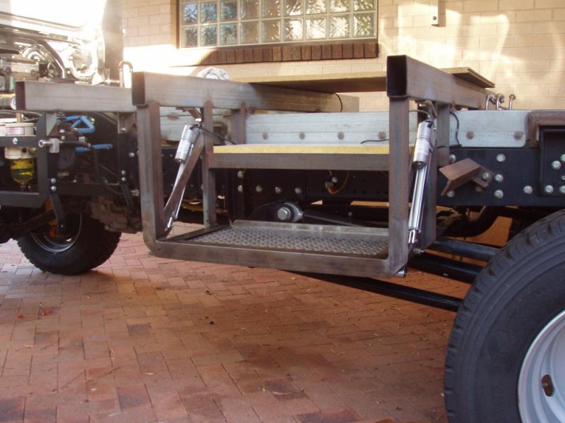
My steps design is not perfect by any means but I do believe that it has some specific advantages over any of the commercial RV steps I have looked at, and I have looked at quite a few. The major advantage is the height of the steps when fully retracted. The steps frame, that is part of the subframe, is made from 50mm angle. When retracted, the bottom step only protrudes about 10mm below this frame, which means that the steps have a negligible effect on the available ground clearance. Another advantage is that the tread length is longer, making it easier and safer to come down the steps.
As mentioned, the Chinese actuators were bought to test the viability of my design. The quality of these actuators is quite reasonable, but the main reason I bought them was because they were cheap. My intent was always to use Linak actuators for my steps if the design worked, but buying them and finding out the design didn’t work would have been a costly exercise, given that the Linak actuators are really expensive.
The Linak LA23 actuators are of a much higher quality, have a higher IP rating and with the same load rating they are about twice as fast.
Now that I have confirmed that my design does actually work, the Linak actuators have been ordered. It will be a while before they get delivered, but as soon as I get them I will swap out the Chinese actuators which are there now. This will involve a few minor changes, as the fixation points are slightly different. I factored this into my design, so this should only be a small job.
Below are a few more images of the steps construction…