 Click any image to enlarge
Installing a set of driving lights is probably the most common upgrade task carried out by anyone wanting more visibility on the road than is provided by the standard headlights.
If you have any electrical know how the installation should be pretty straight forward, but if you don’t, it can be a bit of a challenge.
Obviously, the first decision to be made is which lights you are going to use.
There are a myriad of brands out there to choose from and only you can determine what will work best for you, your vehicle and your budget. The primary lighting options are halogen, HID and LED; each of these having their good and bad points. After deciding on the type of globe, you then have to decide on size, shape and lens configuration. The task can be quite daunting, so a bit of research is probably called for.
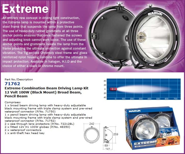
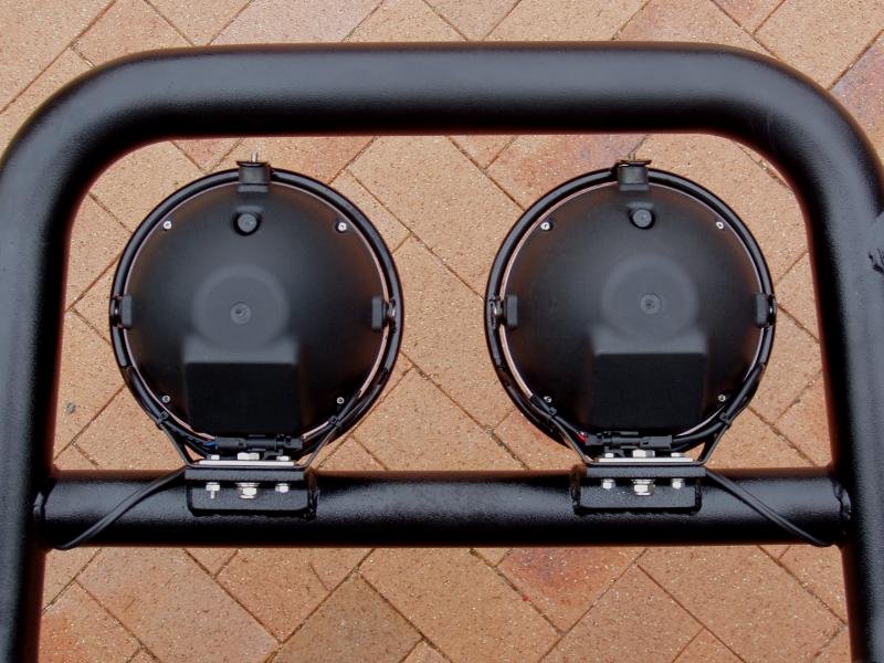
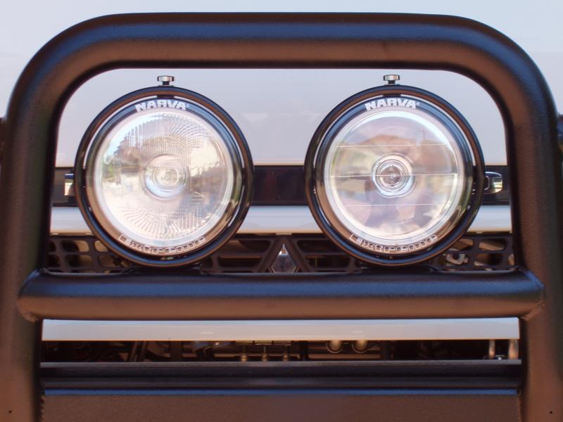
I chose to go with the Narva Extreme Combination Beam Driving Lamp Kit, which includes one pencil beam and one broad beam light. I definitely looked at HID lights and LED light bars, but both of these were quite a bit more expensive than the good old halogen lights I ended up buying. Realistically, I could not justify the additional cost.
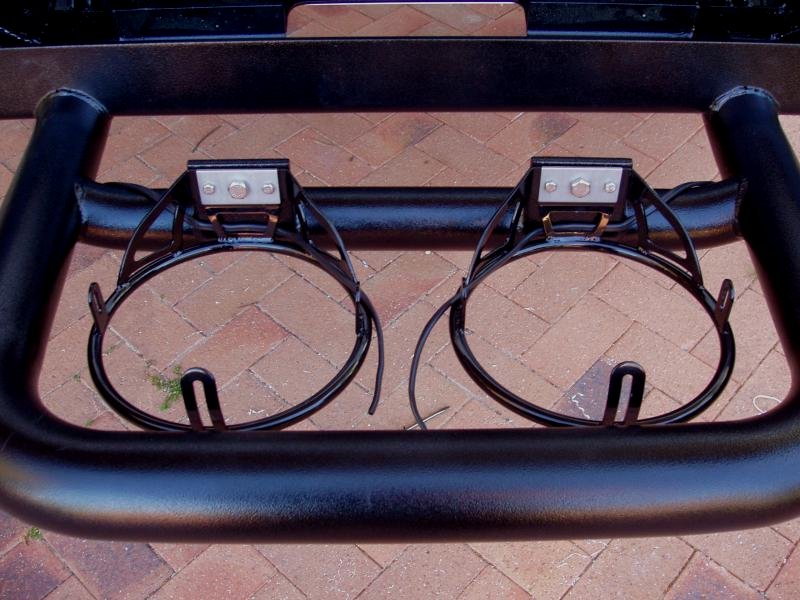
In my opinion, the Narva Extreme is a well built light with a very sturdy mounting system which fitted well on my bullbar.
Now, down to installing the lights…
The first thing I did was to pull the dash apart so I could locate the high beam trigger wire. After locating it, and connecting a multimeter, I found that my truck’s lighting circuit was negatively switched (an earth connection is used to trigger the relay, not power).
I have read lots of bizarre explanations on wiring negatively switched lighting circuits. Apparently this is very confusing to many people.
One way that works, but that I would not recommend, is to ignore the negative switching all together and to tap into the high beam power wire of the vehicle’s headlights (after the high beam switching relay) and use this to trigger the driving lights relay.
What I do not like about this approach is that you have to use a relay switched power source to power another relay. As I said, it works, but there is definitely a better method; it’s called “the right way”.
Connecting the negative wire to the chassis and assuming that it is a good earth is a major reason why people can have poor light efficiency. If using the chassis as your earth, you must ensure that you have good electrical continuity if you want maximum light output.
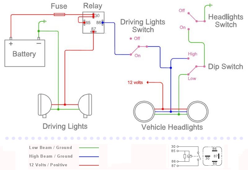
If that all sounds a little confusing, take a look at the schematic, which might help to make the above easier to understand.
Please note that the schematic is not technically accurate; there would be additional relays in the high and low beam headlight wiring circuit.
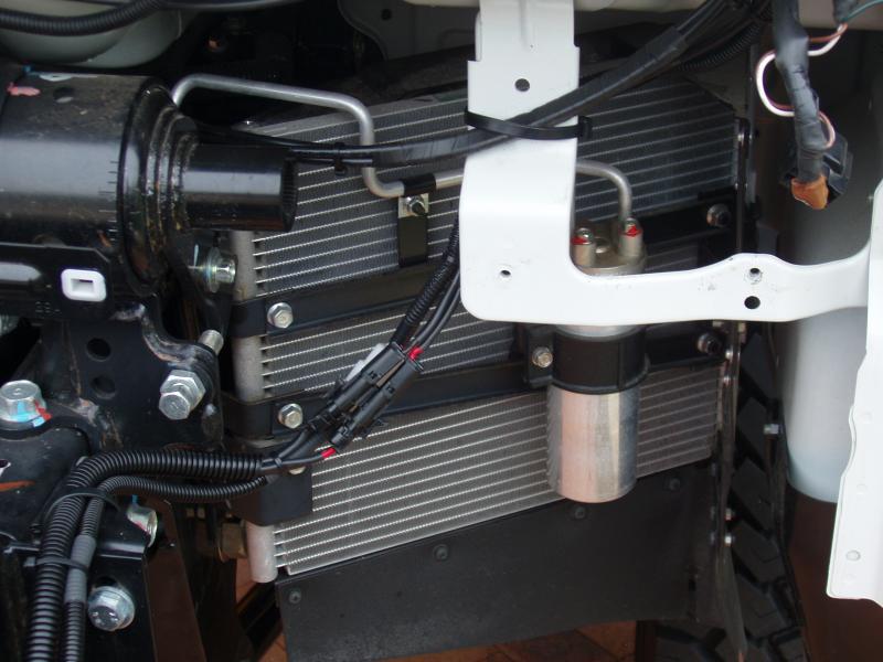
I used OEX 5mm twin sheath oxygen free cable (2.9 mm²) for the driving lights and each light utilises a separate relay. Power for the driving lights relays is supplied by an OEX 6mm twin sheath oxygen free cable (4.59 mm²) wired directly to the truck batteries. Using twin sheathed cable is not really necessary, but it is a nice, neat way of doing the wiring.
I won’t go into wiring size now, I’ll leave that for a separate article. What I will say is that, contrary to what everyone says, size does matter!
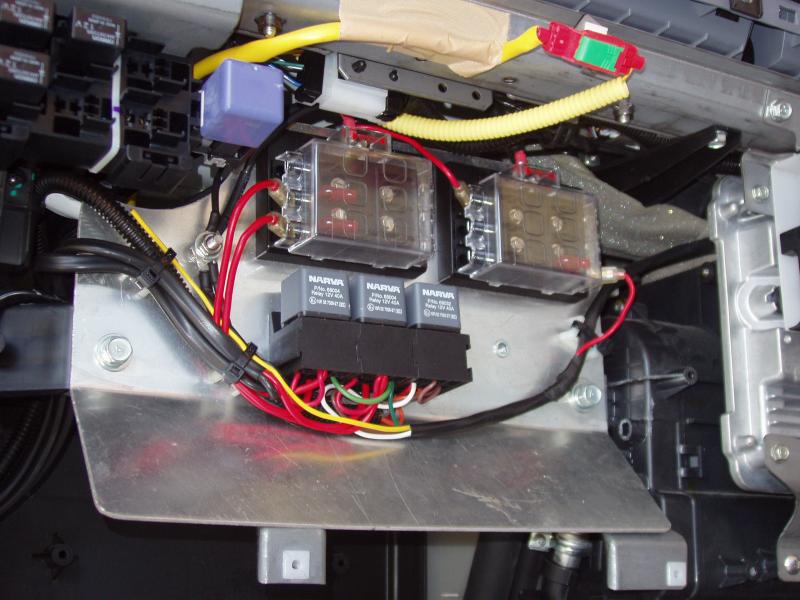
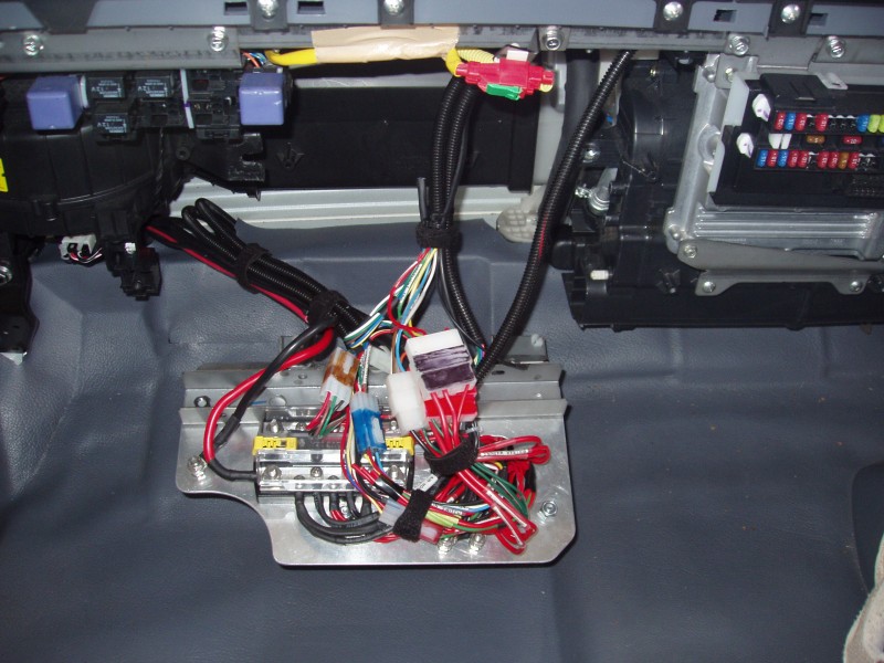
ATW had already installed a dedicated electrical panel behind the dash that housed a fuse block and a relay for the air compressor. Although functional, I did not really like their configuration so I decided to change it to suit my specific needs.
I used two Narva fuse blocks, one of which takes its power from behind the truck’s fuse panel and the other is wired directly to the truck’s batteries. As mentioned above, the driving lights are powered off the fuse block wired directly to the batteries.
I also included the ability to have up to five relays on this panel; currently I am only using three.
When it comes to designing and building things, functionality is definitely paramout, but for me the finished job also has to look good too.
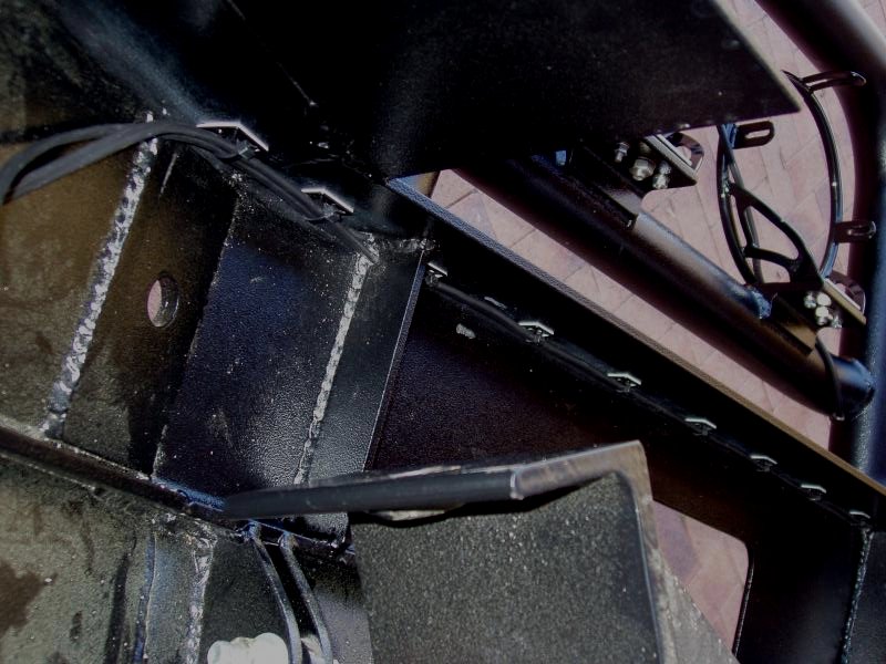
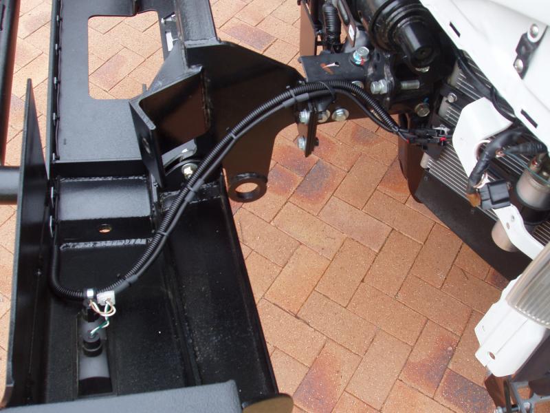
One of the things I don’t particularly like to see are cables and cable ties all over the bullbar. Unfortunately, this is something I see on many driving light installations. I wanted to make my installation as clean as possible, so a bit of planning was involved. The bullbar already had drain holes at either end of the centre cross bar so I simply drilled these big enough to fit my cables through. I also drilled holes up through the bottom and into the centre tubing, so I could get the cabling out.
All of the driving lights cabling was run inside split conduit. This made it very easy to keep things neat.

Well, that’s it. The new driving lights are installed and functional.
Update December 2012
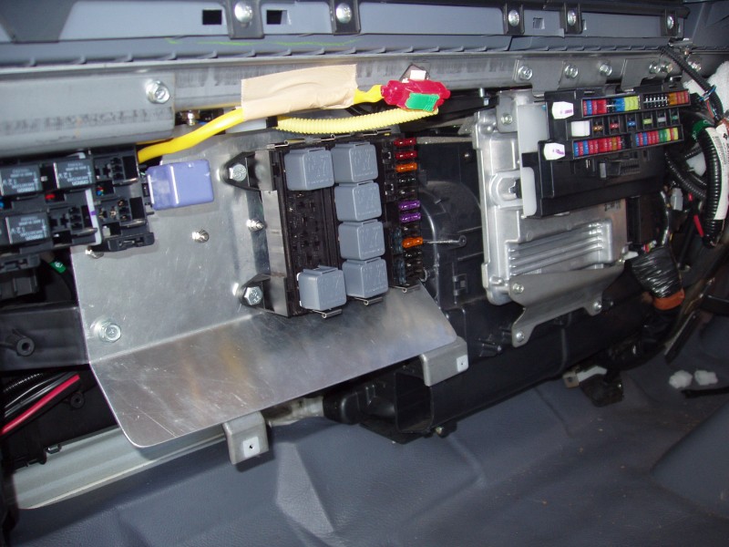
The original power distribution panel has been upgraded to a setup that is neater and has more capacity.
The Narva fuse and relay blocks have been replaced with MTA modular ones. The MTA units allow for the wiring to exit from the rear, which makes for a much cleaner appearance at the front. I decided to make the new distribution panel modular, which allows for relatively easy removal, should additional circuits need to be added down the track. All of the wiring has also been labled, which will help with any future fault finding.
My preferred method for labelling cables is to use a Dymo labeller and clear heatshrink. This method ensures the label will always be there!
A Blue Seas bus bar was used to separate power that comes directly from the battery and ignition power that comes from the main fuse panel.
The original 6mm twin sheath cable (4.59 mm²) that came from the battery was also upgraded to 6B&S twin sheath cable (13.29 mm²), negating any discernible voltage drop at the distribution panel. A 100 amp fuse block was also added to the power cable at the battery end.
Most of this is overkill, I know, but it satisfies my “A Type” personality… 😀