 Click any image to enlarge
When building things you always try to do it right the first time, however, when designing something like a one off custom camper, it is inevitable that not everything goes the way you may have planned it, despite your best efforts.

These dimensional limits apply to vehicles with a GVM of 4.5 tonne or above:
- Rear Overhang Limit (ROHL) cannot exceed 60% of the wheelbase or 3.7 metres, whichever is the lesser.
- Rear Projection (RP) cannot be more than 1.2 metres behind the body.
- Front Projection (FP) cannot be more than 1.2 metres in front of the headlights.
Note: Any Rear Projection must be within the Rear Overhang Limit.
My problem, in a nutshell…
Right at the start of this project I made a small miscalculation with the length of the subframe. The subframe length affected the positioning of the rear bar and tyre carrier and this resulted in the spare tyres protruding beyond the legally allowed overhang. D’oh!!!
The sad thing is that I have always been aware of this “60% rule”, so how I managed to screw this up I still don’t fully understand, but I did.
I have known that my truck exceeded the maximum allowable overhang for a very long time now, but I chose to ignore it, given the amount of effort required to fix the problem. My logic for ignoring the problem was the low probability of ever getting picked up for this excess length.
At this point I should probably quantify that we are only talking about 77mm here, which is just over 3″ in the old speak.
So, what made me decide to fix this problem?
Well, at the end of the day, building something that you know is illegal is never a good plan. There is also the possibility that sometime down the track, when it is time to sell the truck, that this could end up biting me in the arse.
I am now close to the point in this build where I have to commit to the size and design of the camper body. Once that had been done there would not really be a possibility of going back and fixing this problem at a later time. To that end, I decided to pull my head out of the sand and do what was necessary to resolve this self created issue.
At a minimum, the following needed to be done/changed:
- Remove the water tanks and tank brackets from the truck
- Shorten the subframe by 80mm
- Move the rear bar back 100mm
- Redesign the mounting brackets for the external BBQ frame
- Rewire the loom for the rear bar (was hard wired inside the bar)
- Get the rear bar sandblasted then powdercoated
- Repaint modified bracketing
- Reassemble everything
Time to begin…
I started by emptying the water tanks then I removed them from the truck. This was a pretty straight forward task and had the added bonus of confirming that this could be done quite easily. The two spares were removed from the tyre carrier and the crane arm was disassembled. The tyre carrier itself was then removed from the rear bar. The decision to bolt the tyre carrier to the rear bar, opposed to welding it on, proved very useful here. After the tyre carrier was removed the plugs for the rear lights and reversing beeper were disconnected then the rear bar was unbolted and removed. The BBQ frame was the last item to be removed.
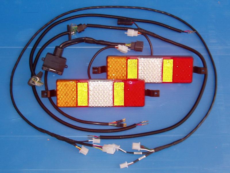
In order to remove the lights and cabling from the rear bar it was necessary to cut the loom. In hindsight it was obvious that soldering and using heatshrink on all of the wires in the loom was not one of my best design decisions. Yes, it was completely waterproof, but it was a little impractical. When I rebuilt the loom I used mini Molex plugs. These plugs aren’t waterproof, so on reassembly I filled all of the plugs with silicone dielectric grease to keep the moisture out. Should I need to replace a light in the future, this will be considerably easier now.
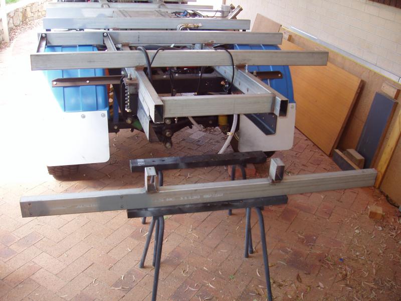
Reducing the length of the subframe involved marking some cut lines on both of the lower subframe rails then, using my trusty little 4″ angle grinder and a cut-off wheel, cutting off the rear rail. It was simpler to replace the rear rail completely, opposed to trying to modify the existing one. As with the other cross rails, some 20mm high blocks were positioned on the new rail and welded in place, then the rear rail assembly was welded to the subframe. Some plates were cut and used to plug the ends of the subframe main rails.
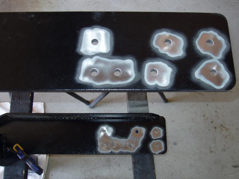
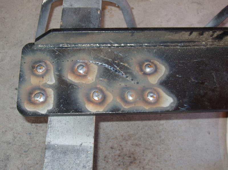
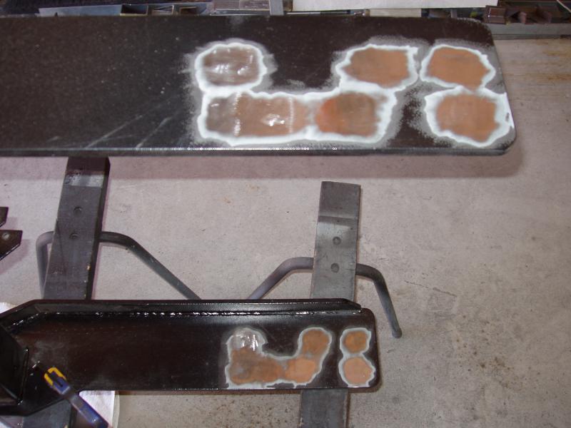
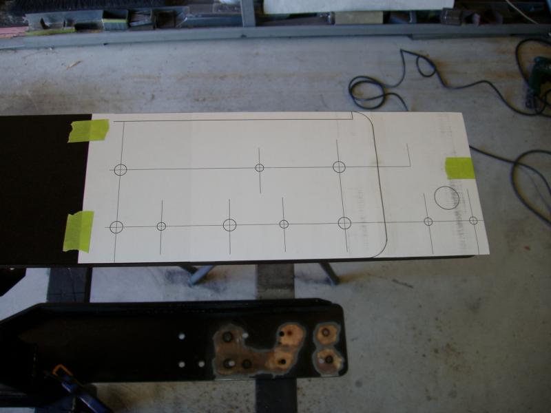
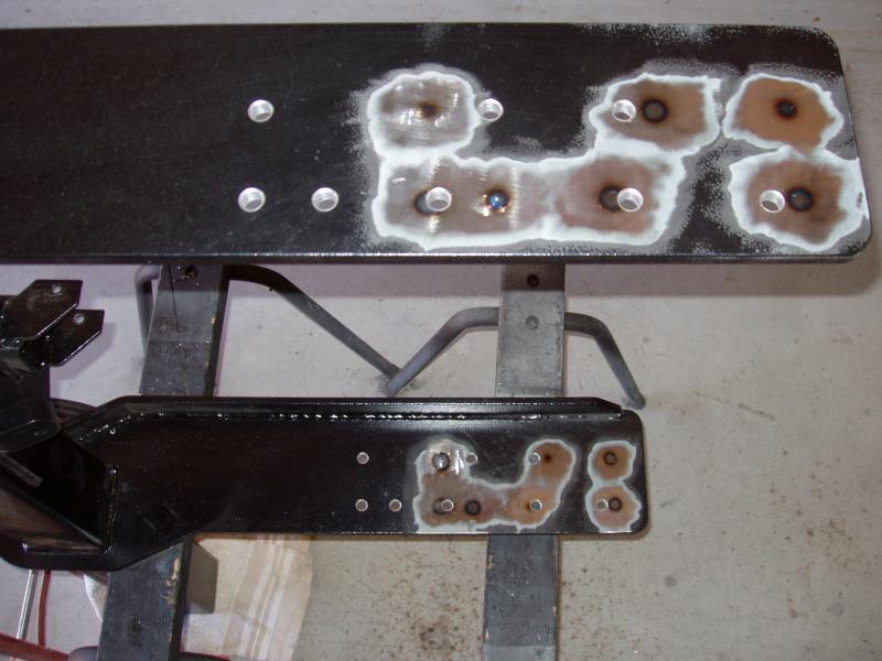
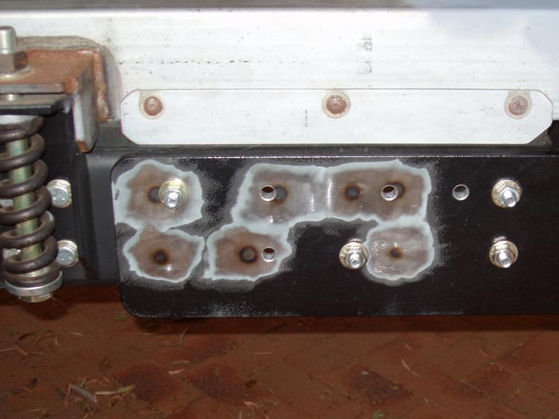
Probably one of the more involved tasks was the repositioning of the rear bar. With the bar positioned vertically and sitting on two saw horses, the existing powdercoating was removed from the area around the mounting holes using a StripIt wheel. A round file was then used to remove all of the paint from the insides of the holes, as welding over paint is never a good idea. After this was done the holes were plug welded then ground flat. Given that I already had all of the chassis holes drawn up in AutoCAD, I chose to use the simple option and printed this out for use as a drilling template. The template was taped to the rear bar and used to mark the hole centres. With the exception of two holes (one on each side), all the other holes were drilled slightly undersized. The bar was then remounted to the chassis. Using the two correctly sized holes as pivot points, the bar was jacked into correct alignment with the other holes. The holes closest to the bar were drilled to the correct size using the existing holes in the chassis as the guide. These were then bolted to stop any movement and the remaining holes were drilled using the same procedure. This method ensured that all of the holes lined up, which is mandatory if the load is to be spread evenly across all bolts.
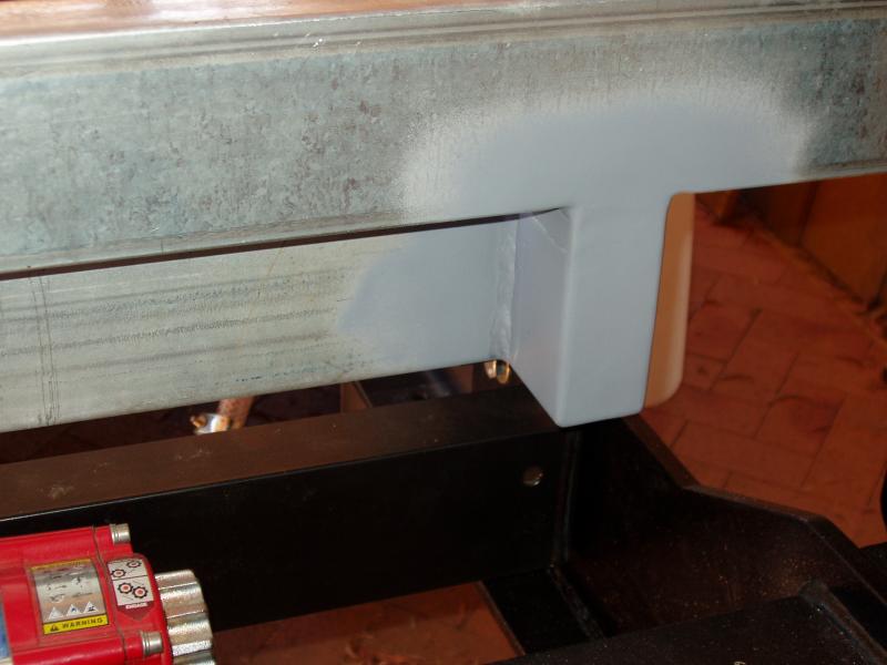
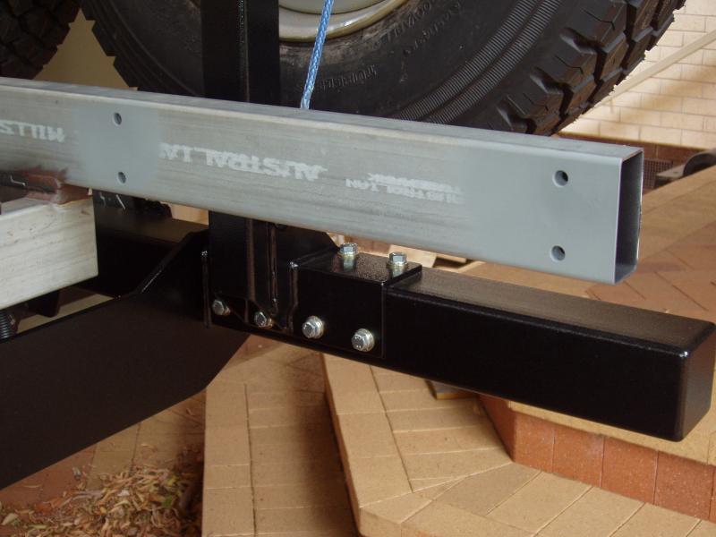
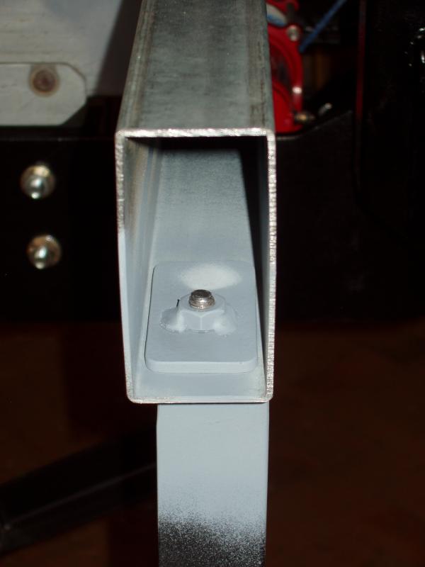
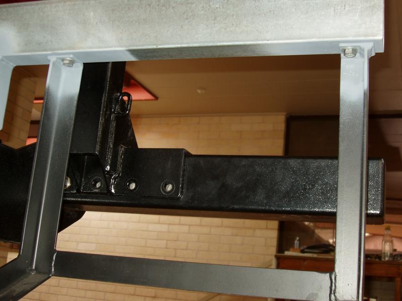
The rear supports for the BBQ frame were initially mounted on the front face of the RHS. With the shortening of the subframe there was no longer enough space between the front face of the new rear rail and the rear wheel to fit the BBQ frame. The rear legs of the BBQ frame were modified so that they could be mounted underneath the RHS. As I have done in the past, I used a captive nut system inside the RHS to distribute the load over a greater area. Mounting the rear legs this way gave me an additional 50mm, which meant the front legs only needed to move forward 30mm, which was doable.
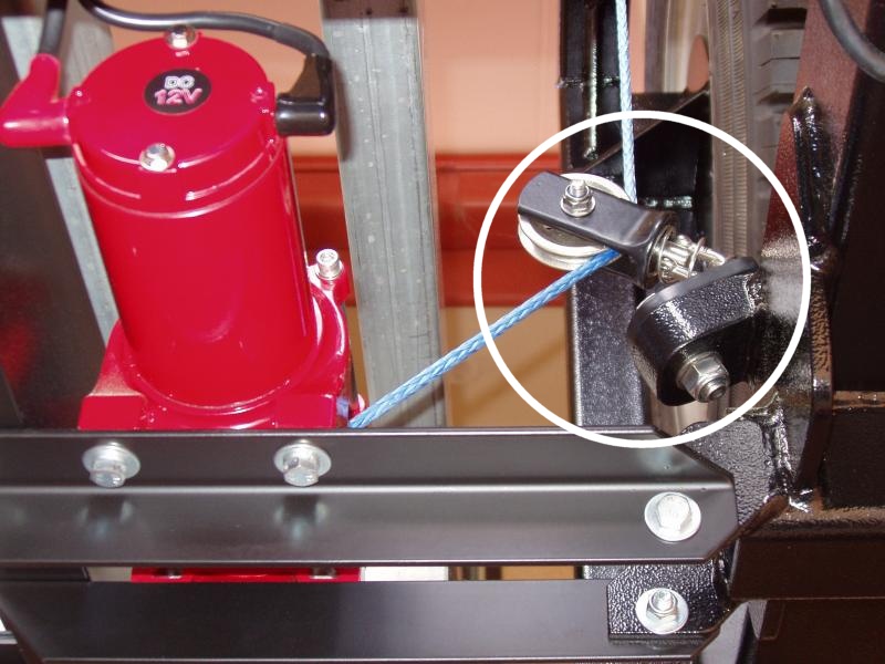
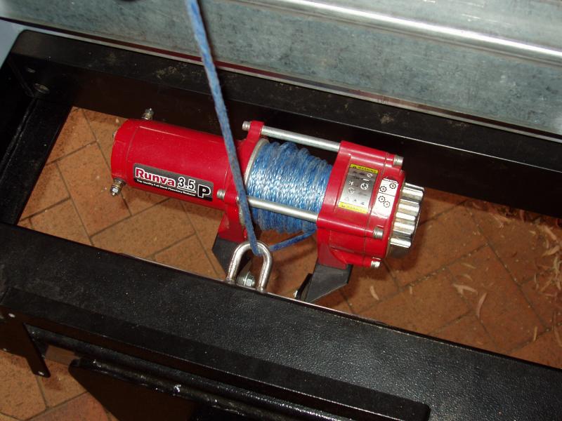
Another small job was modifying the mounting rails for the spare tyre winch. This only involved shortening them by 100mm and redrilling the mounting holes. Given that the rear bar would require repainting, I also decided to make a few other small modifications. My initial design for the winch’s lower roller system, which did not work, utilised a large angled steel block that was welded to the rear bar. This block is not really needed, so I decided to remove it. I looked at using the same, or a slightly modified, pulley system that I had been using, but chose to discard this completely in favour of a simple stainless steel D loop. The winch will only be used infrequently (hopefully) so a simple hawse like system seemed more logical and would have little to no chance of failure.
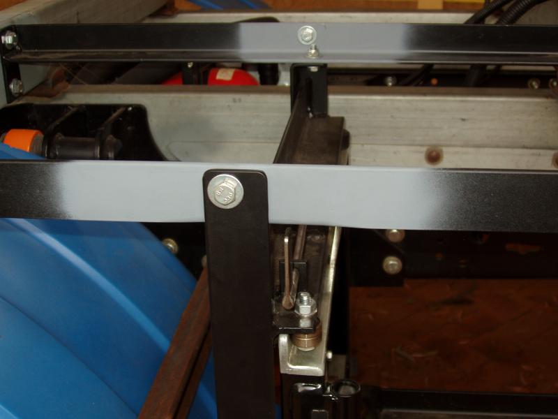
Unlike the older style towbars where the ball mounting plate was bolted directly to the towbar, the Hayman Reese style of towbar has some play between the ball mount and the hitch. I decided to modify my hitch so that this play can be reduced.
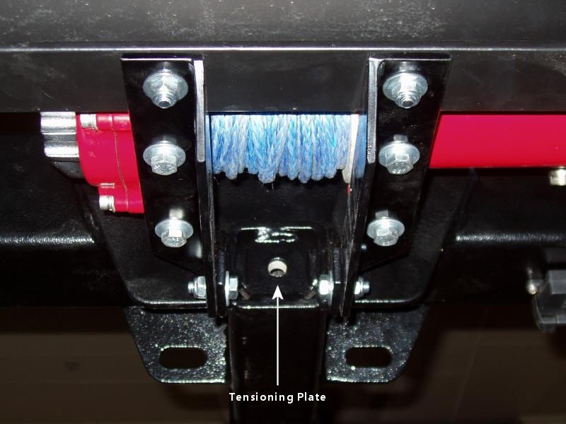
To do this, a 50mm x 50mm x 12mm plate was welded into the rear of the hitch. The plate has a M12 threaded hole in it, which allows a bolt and tension block to be used to clamp the ball mount against the hitch pin.
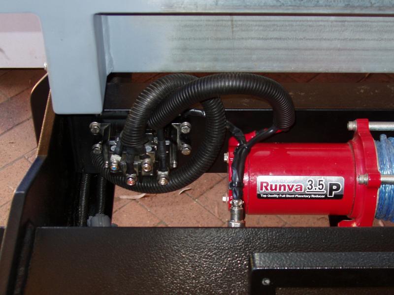
In hindsight, positioning the spare tyre winch solenoid on the subframe was not ideal, so it has now been relocated to the rear cross member. No modification to the existing cabling was required, which made this a simple job. I also removed the wireless controller from the solenoid, as I was never happy with how it worked. Unlike the wired controller which gives responsive on/off control of the winch, the wireless controller had a period of “run on” when you took your finger off the button. This made it very difficult to position the spares when refitting them to the truck.
The final modification that I made here was to improve electrical safety. The power cables for the spare tyre winch run through the same isolator used for the main recovery winch, so for the majority of the time there is absolutely no voltage at the solenoid, which is a good thing. However, if during the operation of the winch a short circuit should occur in either the winch solenoid or the motor, there is a serious chance of fire. To negate this potentially dangerous scenario I have now installed a 100 amp MEGA fuse near the isolator. I will also be installing a 500 amp MEGA fuse in the main winch circuit for the same reasons. I can’t remember why I didn’t install fuses initially, but for some reason I didn’t.
While I am on this subject of electrical safety, I have to say that I am very surprised that the wiring diagrams supplied by various winch manufactures do not include isolators or fuses. I don’t know why this is the case, but personally I think it’s quite irresponsible.
So… at the end of the day nothing really looks any different after making all of these modifications, but instead of being 77mm over the maximum allowed overhang, the truck is now 23mm within the allowed limits, making it totally legal. It’s also safer electrically, so I am happy.