 Click any image to enlarge
Prior to getting back to working on the subframe there was a need to address another issue… how was I going to get the completed subframe on and off the truck by myself?
While working on the individual rear rails it was not too difficult carrying and fitting these onto the chassis but the moment I joined the left and right rails this would no longer be a one person lift.
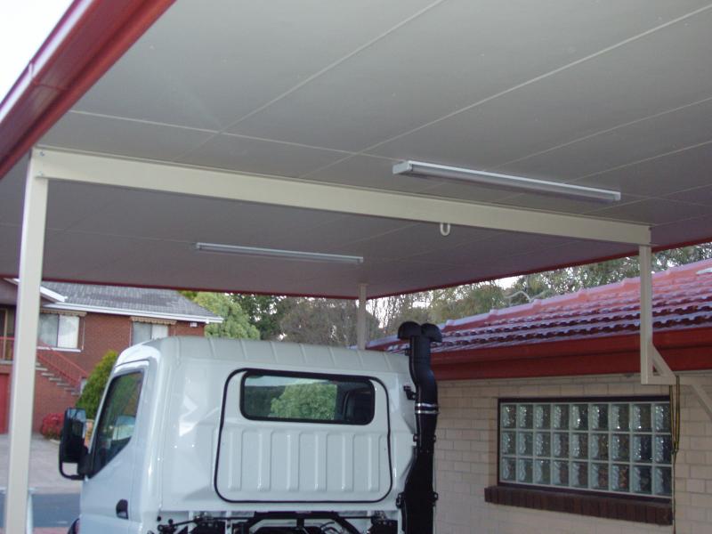
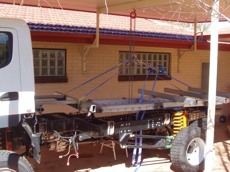
The solution to this issue was quite simple; build a gantry, and what better place to put one than under my carport.
Had I thought ahead, I would have incorporated a gantry into the original carport design. Hindsight is a wonderful thing!
The gantry beam is a 3.4 metre length of 125mm x 4mm C channel, bolted to the centre uprights of the carport. A U bolt was welded in the middle to allow for a block and tackle to be used.
With my right hand now usable again and the gantry complete, it was time to get back to work on the subframe…

The next task was to manufacture the mechanism for attaching the polyurethane to the rear rails.
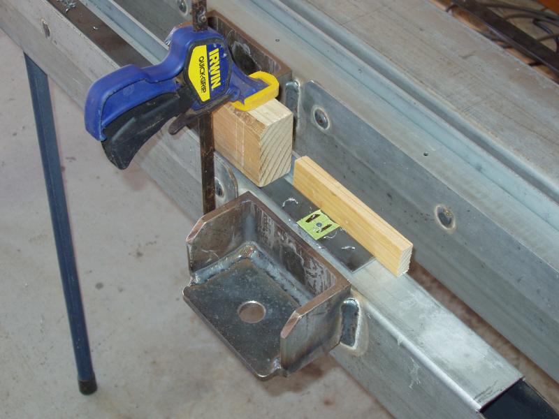
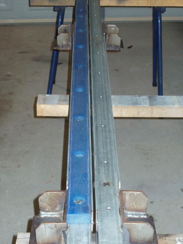
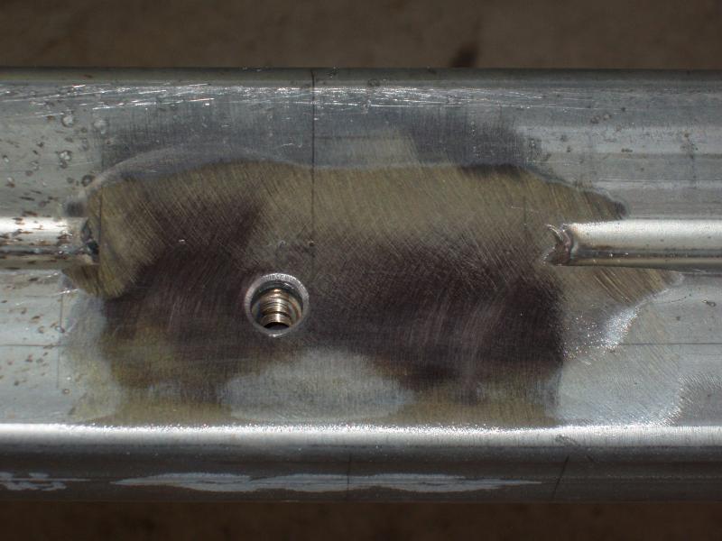
I had toyed with many ways of doing this but in the end I elected to go with a simplistic solution; a length of 25mm x 3mm flat bar with stainless steel nuts welded to it. This bar would be attached to the inside of the RHS by plug welding.
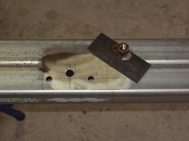
Firstly, the flat bar was drilled with pilot holes then it was positioned and clamped on the rails. This method assured that the holes in the bar would match perfectly with the rails.
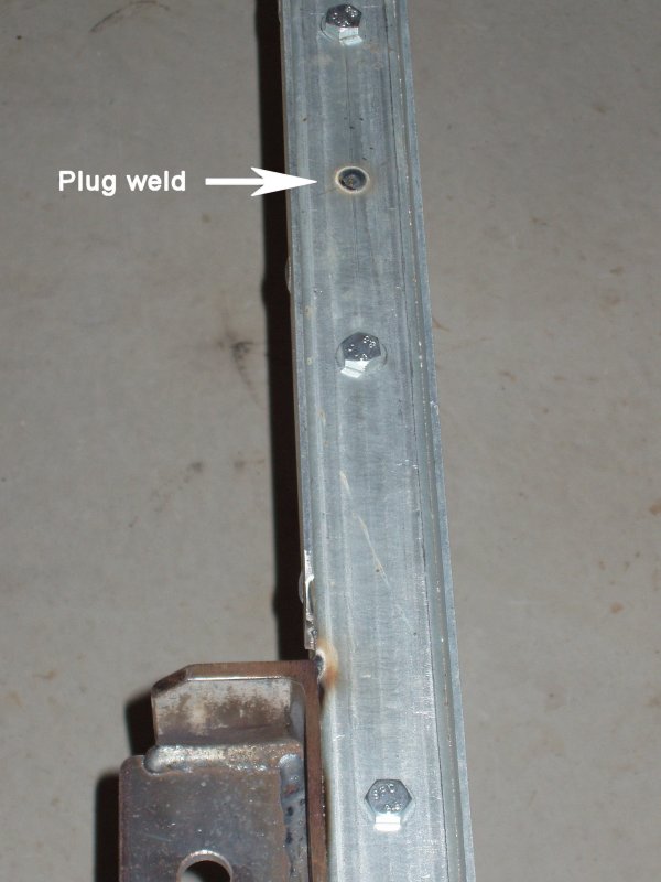
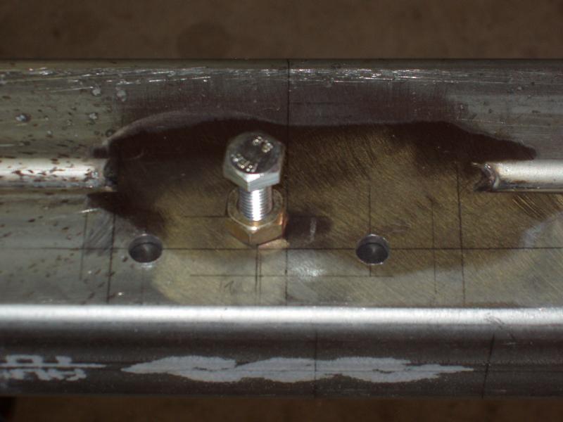
After this was done the rails and flat bar were drilled with clearance holes for a 10mm bolt. Two nuts were welded together, to give more thread contact for the Loctite™ I plan on using, then these were welded to the flat bar (16 pairs of nuts per rail). The flat bar was then inserted inside of the RHS and all of the bolt holes were aligned. Bolts were placed in every hole, to ensure correct positioning, and finally the bar was plug welded to the RHS to secure it.
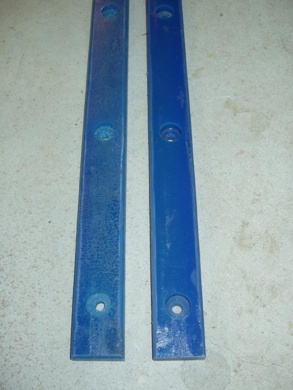
I am using 50mm wide by 25mm thick polyurethane bar as a cushion between the subframe and chassis. This was definitely not the cheapest option, so I hope it works as I have designed it. The primary rationale behind this approach is to distribute the load of the camper body over as much of the chassis as possible, eliminating point loads and reducing stress points.
The polyurethane was cut to size (to fit snugly between the flat bars I had welded on the sides of the RHS) using my saw bench; not the most ideal way to do this, but it worked. Holes, that matched the ones in the RHS, were drilled and counter bored (to set the bolt heads below the surface). That completed most of the work required for the bottom rails; the bottom rails being the most involved part of the subframe.

A small digression here…
For anyone that is interested, bolting into hollow steel sections (RHS or SHS) is easily done by welding nuts to a flat bar or plate then plug welding the bar to the inside of the the hollow section.
The plans for the front section of the subframe were changed numerous times before I settled on a final design; hmmm, that sounds familiar…
Although definitely not the hardest section to fabricate, this is arguably the most important area of the subframe as it is above the step in the chassis and therefore encounters the most amount of torsional stress when the chassis flexes.
Life would have been considerably easier if I were willing to run a single rail from the back to the front, but I wasn’t. The primary reasons for not doing this was my intent to have the top of the camper body no higher than the roof of the truck’s cab and that I wanted to “hang” things from the subframe cross bars. If I were to run a single rail I would have lost another 50mm in height. That may not sound like much, but for my design every millimetre matters. So, I over-engineered this area, keeping it low but making it stronger. Having unbroken cross bars is stronger than welding extensions to the sides of the rails. Unfortunately you cannot have it both ways; you just have to choose the design with the most benefits.
I usually build things stronger than they need to be, following the old adage of “better safe than sorry”. You may lose out a little because things are normally heavier if this approach is used but, in my opinion, the piece of mind you get normally outweighs the negatives.

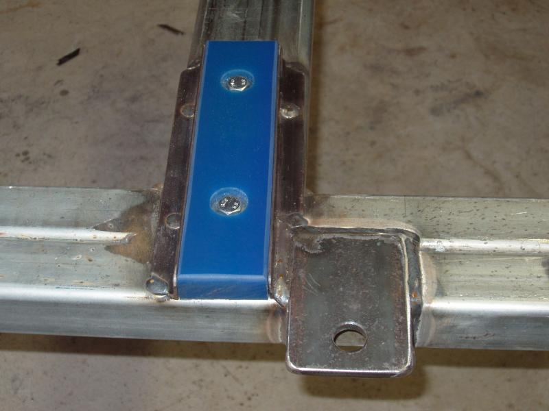
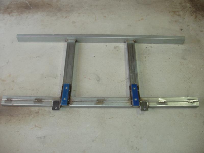
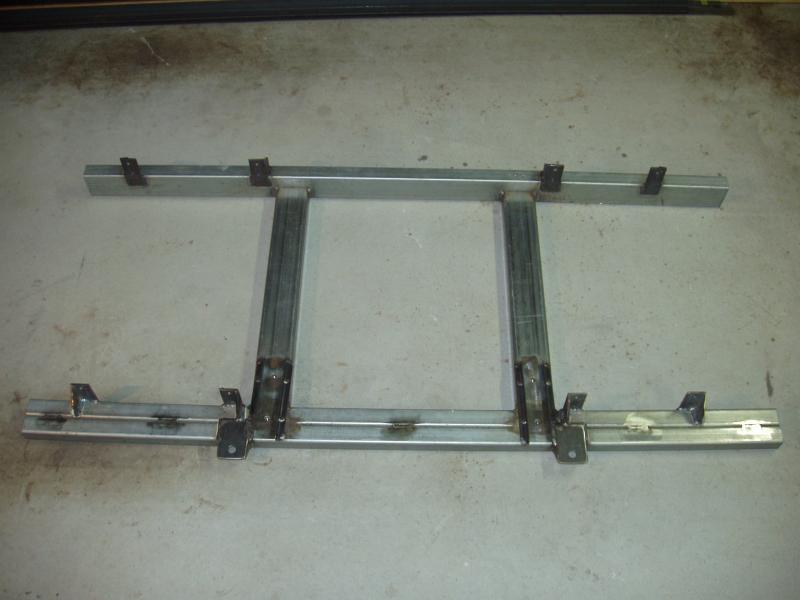
The front part of the subframe is a small ladder section. The front beam is made from two 50mm x 50mm x 4mm square hollow sections (SHS) welded side by side. The rear beam is a 100mm x 50mm x 2.5mm rectangular hollow section (RHS) and the two are joined together by two lengths of 100mm x 50mm x 5mm RHS (parallel with the chassis rails).
As with the rear rails, polyurethane bar is used as a cushion between the subframe and the chassis. Because of the step in the chassis, the amount of polyurethane in the front is limited to two short lengths, each being 240mm long (about 130cm² of support per side). Each polyurethane bar is held in place with two bolts (screwed into the subframe) and some 20mm angle iron on each side (for lateral support). The supports for the polyurethane are angled slightly to match the shape of the chassis, giving the greatest possible contact area.
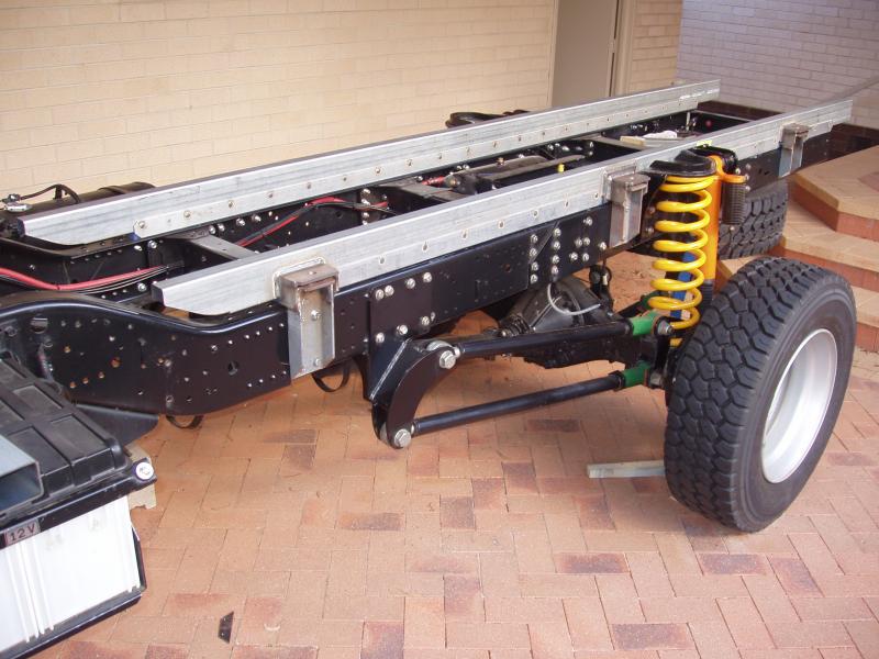
Behind the chassis step it is quite straight forward fitting the spring mounts but there are a few things at the front end of the chassis that need to be worked around. For this reason the front subframe mounts, although similar to the rear mounts, had to be designed slightly differently.
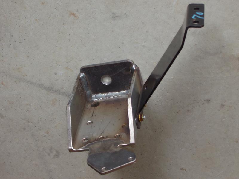
The passenger’s side is simpler, only requiring a pass-through hole to allow affixing the existing cable clip on the inside of the chassis rail.
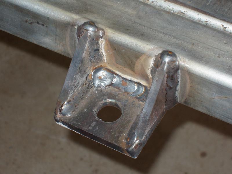
The top section of the spring mounts are pieces of 110mm x 75mm x 8mm flat bar welded to the underside of the front subframe rail. Additional support is provided by welding webs at either side of the flat bar. This design was used as it has a lower profile than the rear mounts.
The front spring mounts do not provide any fore, aft or lateral support for the subframe. This is intentional as it allows for more freedom of movement when the chassis flexes; the chassis flexing being greatest in the area of the chassis step.
One of the things I wanted to do with this subframe build was to remove as many torsional loads from the chassis rails as possible. The two main items that create this kind of load are the standard fuel tank and the truck’s batteries. A new, larger fuel tank will be located between the chassis rails and the original tank will be discarded. I will go into more detail about tanks in a future article.
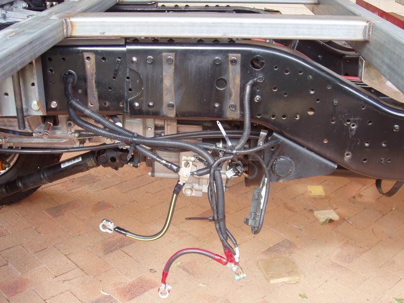
The plan is to offset the weight of the truck’s batteries by mounting the house batteries in the same location on the opposite side. That will happen when the new fuel tank is installed and the original tank is removed. That cannot happen until the truck has been registered and the new exhaust has been fitted. It’s like one big jigsaw puzzle…
In order to have a flat deck it was necessary to weld 20mm spacer blocks onto the rear rails in order to get the correct height for the cross beams. As expected, welding on the spacer blocks had the effect of bowing the rails. No issue… a bit of time with the workshop press got them back to being straight again.
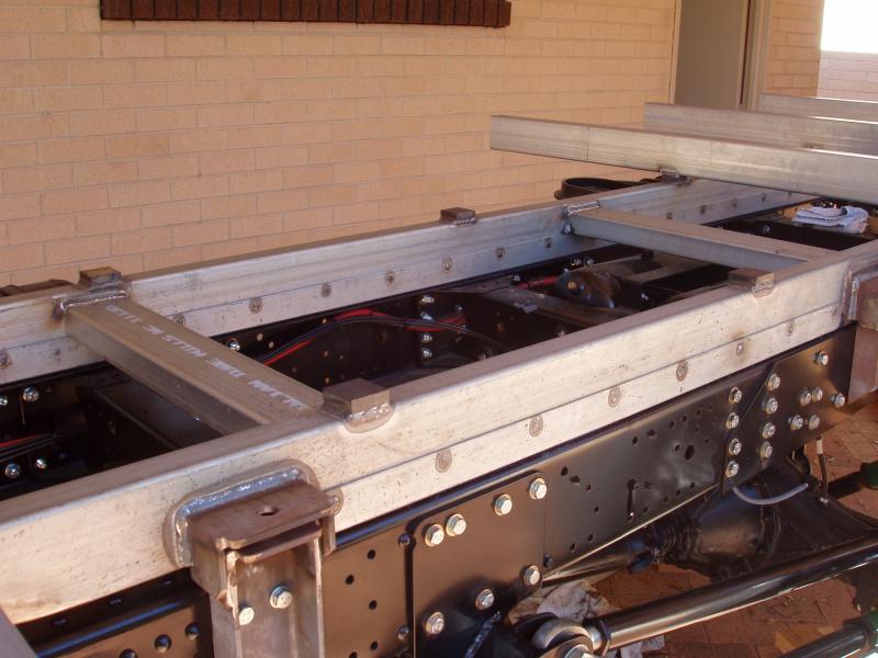
My original plan was to weld everything together in the garage but I had a sanity attack and decided that it was going to be much easier to do this “in situ”. There are three cross members used to space and strengthen the rear section. Additional support was also added where the rear rails join with the front section. The rear section has five cross beams spaced at approximately 750mm intervals. These are welded on top of the spacer blocks.
Part 3 of building a subframe system will detail the final parts of the subframe build, including the completion of the battery frames and the entry area (steps) for the camper.