 Click any image to enlarge
Finally, after much waiting, I have received everything that I needed to start work on my subframe system.
I thought that this part of the build would be fairly straight forward but, as is often the case, it doesn’t always work out exactly that way.
I have to say that there was a lot of time spent evaluating various options before actually settling with what I thought would be a workable subframe design. I started out by “dry fitting” lengths of wood and steel along the chassis, trying to get a feel for dimensions and to work out how many, and where, I would be able to put my spring mounts. The challenge was, wherever possible, to position the mounts where I could utilize existing holes in the chassis rail. I finally decided on an eight mount system (four per side), each mount being fairly evenly spaced along the chassis. Only two rivets on the left hand side required removal and I needed to drill two additional holes in each side in the area just in front of the rear suspension coils.
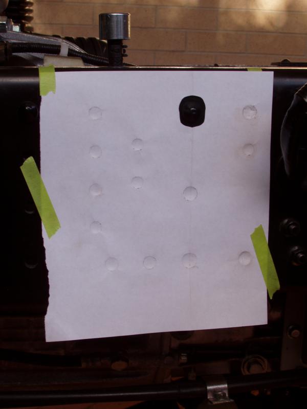
To start with I needed to determine the existing hole positions in the chassis rails so I could transfer that information into AutoCAD. I used a very simplistic method to do this, taping pieces of paper over the specific areas and using a small ball pein hammer to mark out the holes. When this was done I simply marked out all of the hole centres and determined the exact hole positions. This was much simpler, and more accurate, than trying to measure directly off the chassis.
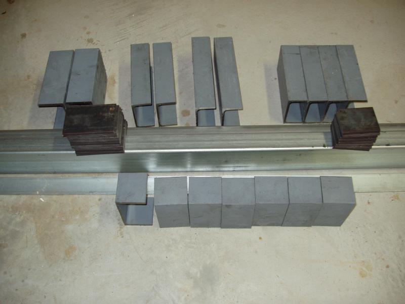
The spring mounts are made from two different sections of structural C channel; 100mm and 125mm and the top plates are from 8mm flat bar. The subframe is primarily made from 100m x 50mm Rectangular Hollow Section (RHS) and 50mm x 50mm Square Hollow Section (SHS).
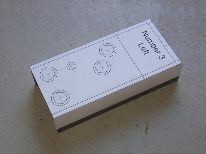
Given that AutoCAD can easily plot drawings at a scale of 1:1, I figured that I would take the easy way out and print the individual drawings for each of the lower spring mounts and use these for my marking out of the hole positions. I could have marked out the hole positions directly on the C channel but the printed drawing method proved to be a simple and very accurate way of getting the holes in exactly the right position. I have never done my marking out in this way before, but I would definitely consider doing it again, if the part allowed for it.
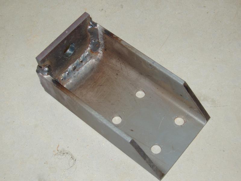
The six rear spring mounts are a fairly simple design. The mounts are made up of a lower and upper section connected by a 9″ x ¾” UNF grade 8 bolt and a 150mm long spring. The lower part of the mount is made from 100mm structural C channel with an 8mm plate welded across the top. The upper part of the mount is made from 125mm structural C channel, also with an 8mm plate welded across the top.
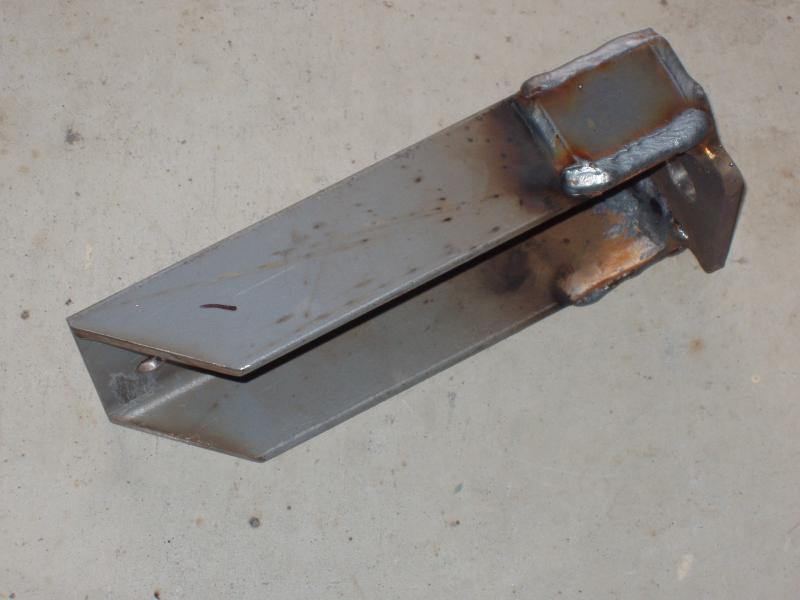
After looking very closely at how some other spring mount systems were designed I was a little concerned to see that the control of fore and aft movement was left to the bolts that attached the upper and lower mounts. Personally, I did not like the idea of that. To that end, I designed my mounts to provide fore, aft and lateral support. This was achieved by welding spacer plates to the sides of the lower C channel. There is a maximum of 1mm of clearance between the top and bottom mounts. The bolts do not have any sheer forces applied to them.

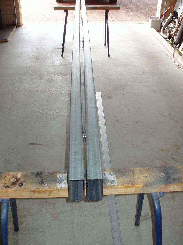
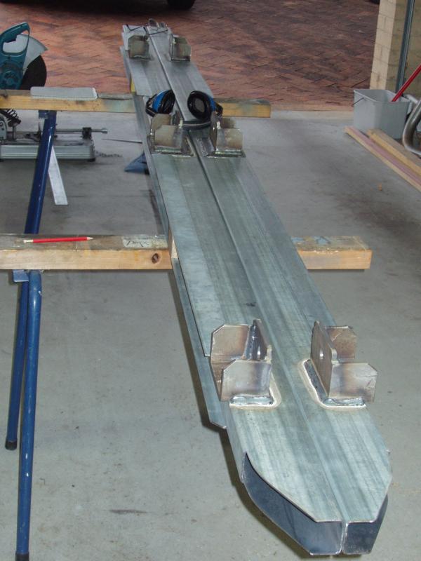
Because I like to make things look “pretty”, I cut the bottom rails of the subframe to match the curves and angle of the step in the chassis. I could have simply cut the RHS at an angle, but that wouldn’t be me. The fronts of the rails will have a plate welded on to them to seal them up and to enhance the strength of that area.
My design uses a 25mm polyurethane bar as a separator between the chassis and the subframe. The rationale behind doing this is that the load from the camper body can be spread out more evenly along the entire chassis, reducing point loads and localized stress points. One of the things I wanted to avoid was sideways load on the polyurethane and the bolts that attach it to the subframe. My solution to this issue was to weld a 50mm strip along the sides, effectively cupping the polyurethane in a solid channel. These strips were plug welded to the RHS.
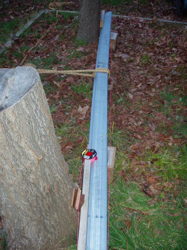
One of the side effects of welding is that you often get bending where you don’t want things to be bent. Sometimes you can avoid this by planning the order in which you do your welds. If you have areas to weld on opposing sides, the welds stresses can sometimes balance each other out. If on the other hand you are only welding on one side of your work then bending may be unavoidable. Basically, bending happens when you weld stuff; you just have to deal with it.
It may not be too obvious in the image on the right, but there is about a 20mm bow in each rail.


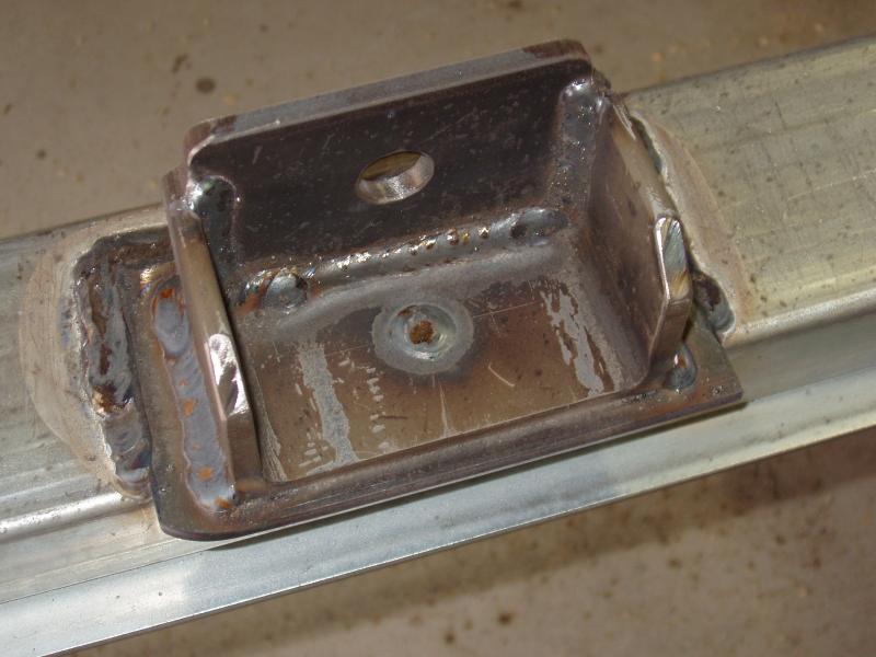
The image on the right shows the top mount welded to the spacer plate. Again, it is welded on three sides and plug welded in the middle. The plug weld has to be ground flat as the rear surface of the C channel, along with the sides, are used as guide plates.
With quite a bit of toing and froing from the garage to the truck and back again, the front and rear mounts were positioned and welded onto the lower subframe rail. I chose to do it this way, rather than using a tape measure, because of the very tight tolerances I gave myself. As I mentioned earlier, there is no more than a millimetre of lateral movement between the upper and lower mounts. Thinking about this, that tight a tolerance may prove to be a bit too close. If I choose to loosen this up a bit it’s just a case of grinding a bit off the sides of the lower mounts.
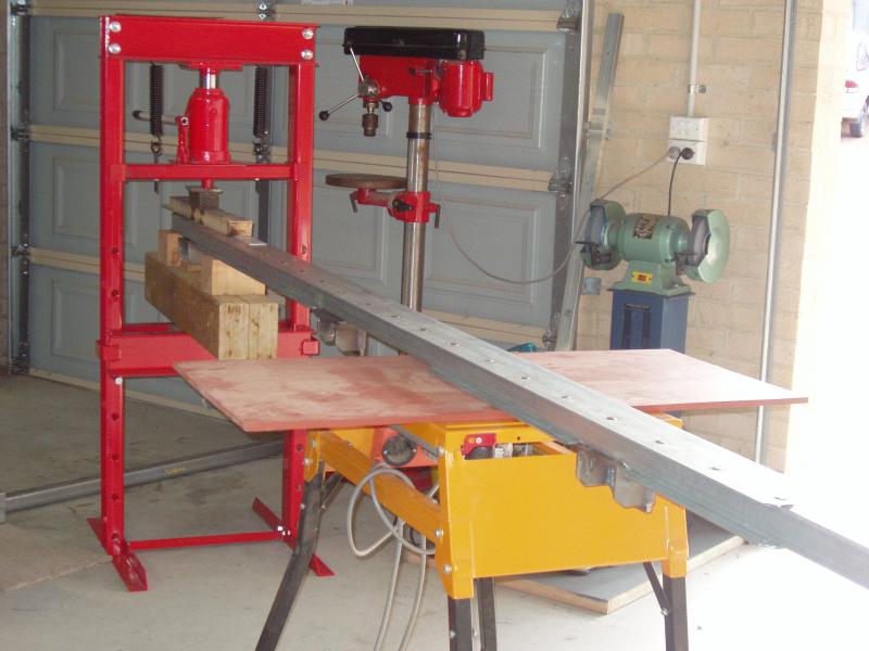
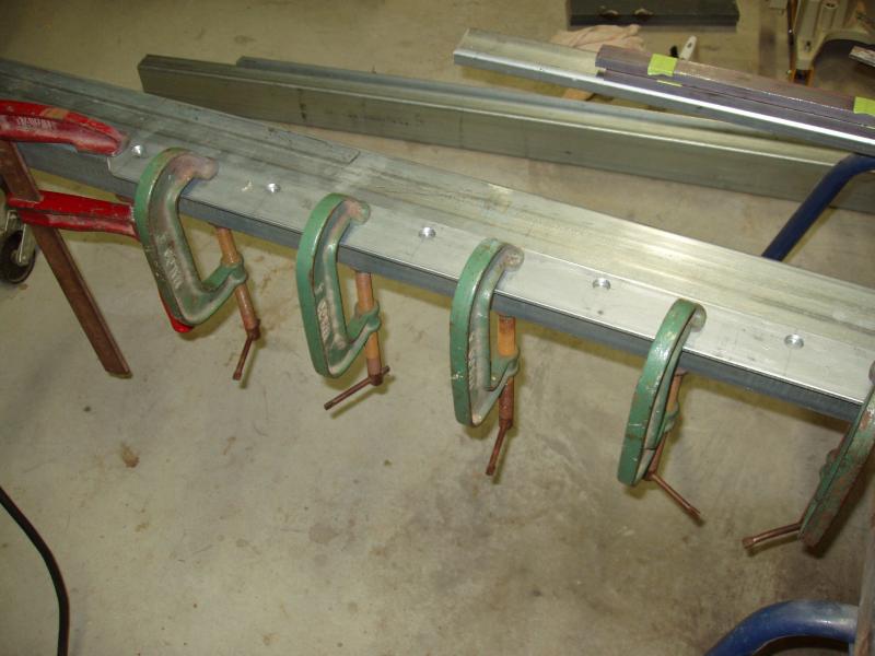
As I expected, with welding all of the mounts on one side there was some more bending of the RHS. This time however straightening those bends with my tree and winch solution was not really viable, given that the bend was not a simple bow; there were noticeable bends at each mount point. The solution was simple, buy a workshop press.
With the press I was able to accurately bend the RHS and achieved the desired result; nice straight subframe rails.
Unexpected cessation of work.
All was going really well until I stopped work to talk with a neighbor who was walking by with his three dogs.
Without any provocation one of his Rottweilers attacked me, biting my right hand.
Unfortunately, because of this incident I have been unable to work for about a week now.
Slowly my hand is getting better and I hope to get back to working on the subframe pretty soon.
As would be expected, I am not a happy camper at this point in time.