 Click any image to enlarge
The past few weeks have been spent building a multitude of brackets, or modifying existing ones.
Brackets for the new fuel tank and for the calorifier needed to be in place in order to position the exhaust hanger brackets correctly.
The bracket built by ATW to house the air receiver and second vacuum tank was engineered very well; unfortunately it was positioned centrally between the chassis rails, which did not allow me to position the exhaust as I wanted.
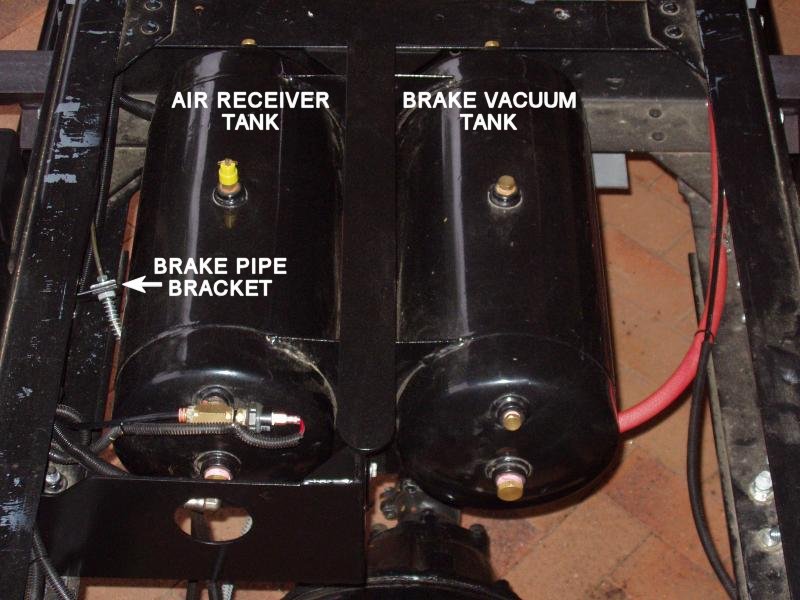
After completing the modifications to both brackets I resprayed them and refitted them to the truck and connected everything back up.
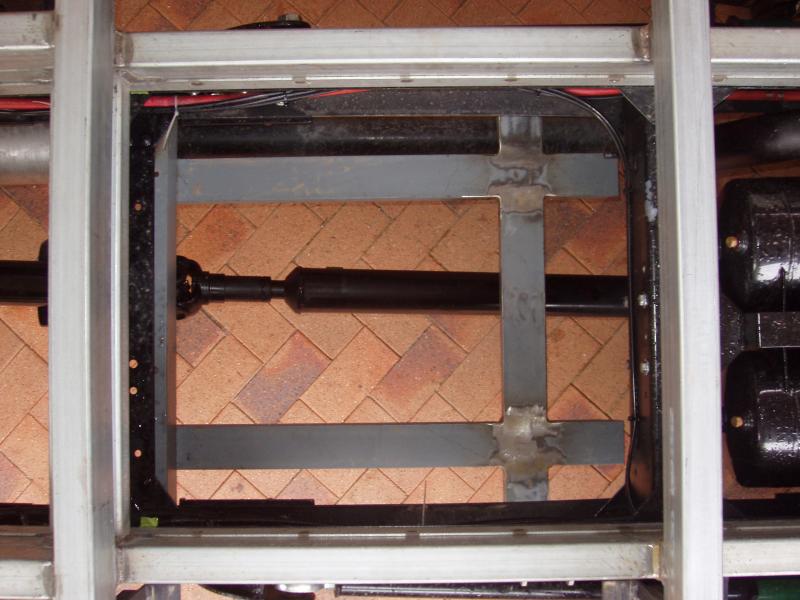
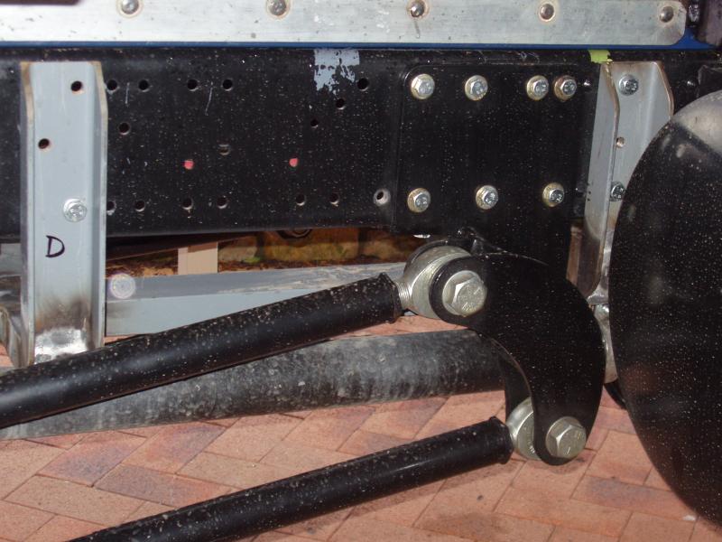
I also spoke with John, from ATW, and suggested that the design for the Watts Link be modified.
Currently the driver’s side support bar is about 4″ higher than the one on the passenger’s side. Mirroring the Watts Link would mean that the support bars would be on the opposite sides to what they are now. Mirroring the Watts link would have no functionality difference, but it would definitely make running an exhaust easier.
A new custom made 200 litre aluminium diesel fuel tank will be fitted between the chassis rails. This will replace the original 125 litre steel tank (115 litres in reality) that now hangs off the side of the chassis. Centrally mounting the fuel tank will reduce torsional stress on the chassis.
I needed to design a suitably strong fuel tank support bracket, given that the new tank will weigh in at a little over 200kg (when full).
The tank bracket consists of a front and a rear section. Both sections are manufactured from 75mm C channel bolted to the outside of the chassis rails, in the same manor as the spring mounts. The two sections are bolted together at the front, not welded. Doing it this way will make removal of the fuel tank easier, should that be necessary in the future.
The front section of the tank bracket will also be used to secure the bottom rails of the calorifier rails. Another reason why the tank bracket was designed in two sections.


An Isotemp stainless steel 30 litre calorifier is located in the bay in front of the fuel tank. A simple 40mm angle bracket is used for the front part of the calorifier bracket. Two 50mm x 20mm rails run between the front of the tank bracket and the angle bracket; the calorifier will be bolted to these rails.

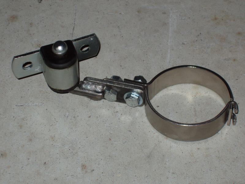
With most after market exhaust systems the exhaust shops normally use generic exhaust hangers and weld these directly to the exhaust pipe. As much as this is functional, I do not like this concept, so I made my own hangers and modifed them to suit my needs. The exhaust hangers I made allow for easy removal of the exhaust system. Sourcing the 76mm tang clamps was the only real challenge.

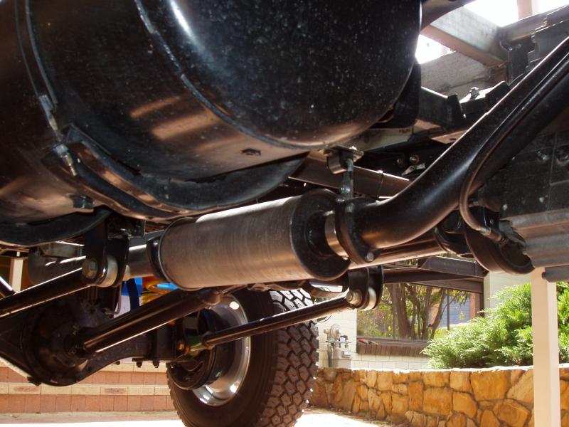
The muffler I chose to use was a Proex megaflow UNXSTR127 (6″ diameter, 18″ long). This muffler has virtually no gas flow restriction. It is positioned toward the front of the truck and sits slightly higher than the bottom of the transfer case. Unlike the standard exhaust system, there is no flex joint in this new system.
I was convinced by the guy at the exhaust shop, who has over 35 years experience, that a flex joint is the weakest part of the system and that a well designed exhaust does not need one.
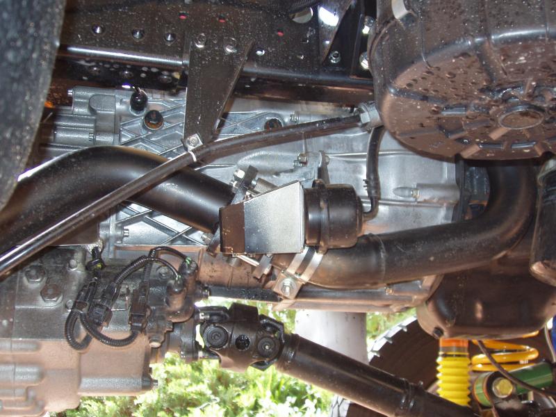
Directly after the manifold flange the exhaust goes from 2¼” to 3″. The 3″ retarder (exhaust brake) sits in exactly the same location as the original retarder. It fitted in with a very minimal modifications to the original engine bracket.
I don’t know if the new exhaust has given the engine any more power or torque, as I did not do any before and after testing.
Given that I needed to replace the original exhaust in order to position my tanks within the chassis rails, going to a 3″ system just seemed like a logical decision; if I get some more power, that’s just an added bonus.