 Click any image to enlarge
When it comes to heating there are many options to choose from.
For my water heating I decided on using a calorifier (heat exchanger) and for cabin heating I will use reticulated coolant and a radiator/blower setup. A heated towel rail will also be included in the bathroom.
This part of the project has proven to be the most problematic, frustrating and time consuming for me so far.
Rather than just presenting my final solution, I have chosen to write a “warts and all” article that also describes my failings and bad decisions.
Maybe others can learn from my experiences and avoid making similar mistakes themselves…
I apologise in advance, as this article is quite long winded.

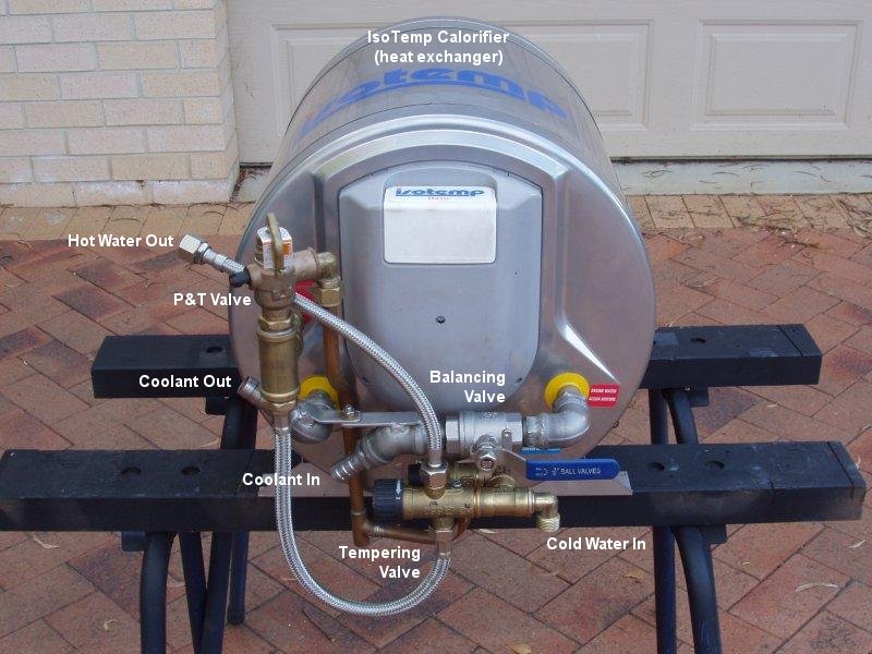
Initially I purchased a 20 litre Sigma Marine calorifier but I returned it because I was not happy with its build quality. The calorifier I have now is an IsoTemp Basic 30, which is a very nicely made, fully stainless steel unit, opposed to the Sigma Marine calorifier, which had a stainless tank with an ABS cover.
This IsoTemp calorifier has the option of being heated via a 240 volt element, but at this stage I do not intend to utilise that feature, in fact I have disconnected the power cable and removed it from the unit.
Using a calorifier is an efficient way of obtaining “free” hot water while the truck is running. Heated coolant is routed from the truck’s cooling system through the calorifier’s heat exchanger coils, heating the water to approximately 80°C. A tempering valve is used to reduce this temperature because water at 80°C is too hot for normal domestic use. The tempering valve works by mixing the hot water that comes out of the calorifier with cold water from the fresh water tank, resulting in hot water being delivered to the camper at a safer temperature. A secondary benefit of using a tempering valve is that the volume of available hot water is increased from that held in the calorifier tank. My 30 litre calorifier should be able to yield 40 litres, or more, of usable hot water.

The truck’s engine coolant will heat the calorifier when the truck is running, but if you are camped for an extended period of time and don’t want to start the engine to get hot water you need to have other options. As mentioned, this particular calorifier did have the ability to be heated electrically, but that would only have been viable if there were a 240 volt power source available. We intend to be free camping most of the time, so having ready access to 240 volt power is unlikely.
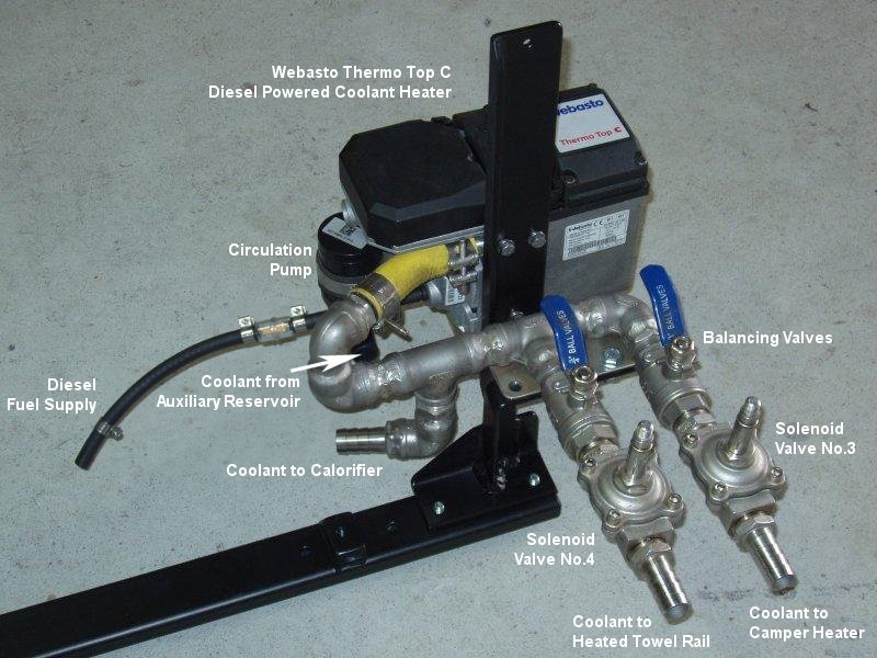
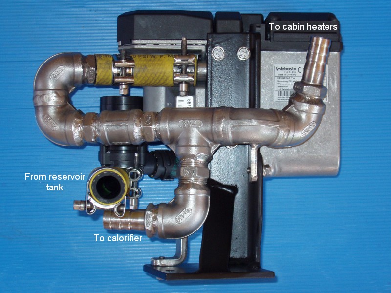
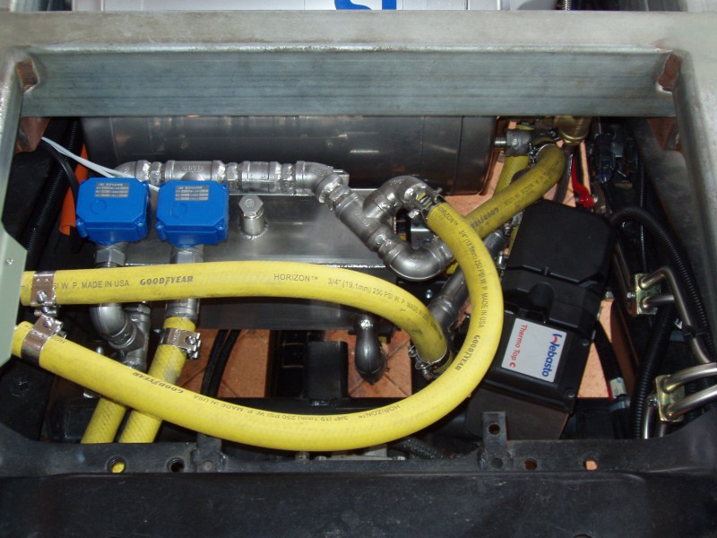
An alternative, and the one I have chosen to go with for my design, is a Webasto Thermo Top C. This unit is a self contained, diesel powered boiler, designed to heat coolant and circulate it through the system.
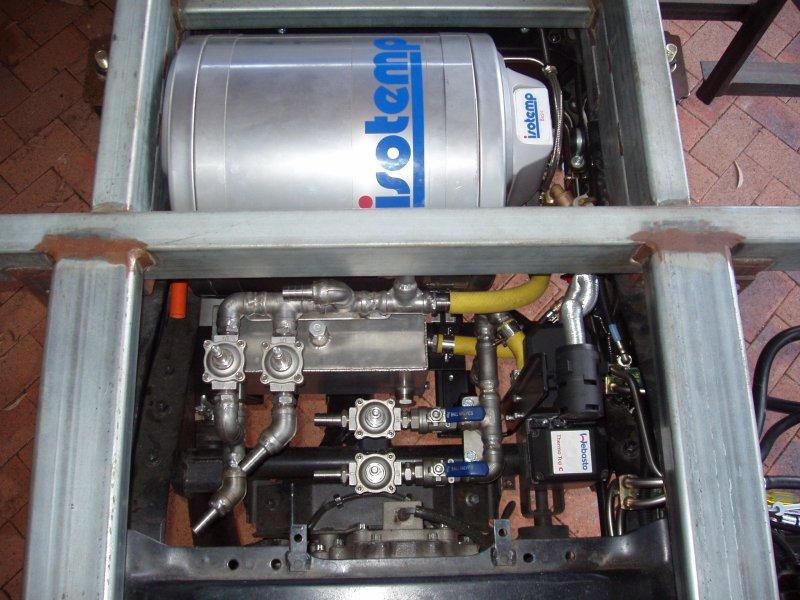
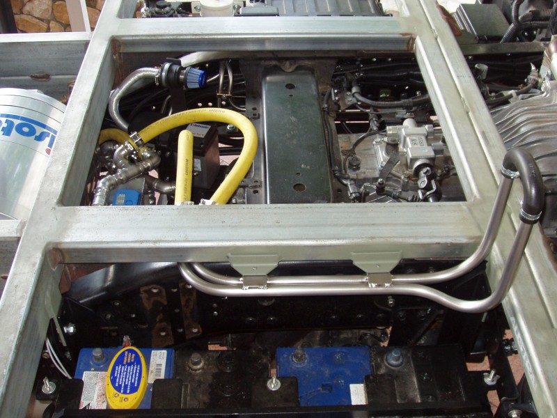
I determined that the best location for the heating system would be between the chassis rails in the first bay, directly behind the transfer case, so this was taken into account when designing the camper’s subframe. Space is limited in that area, but everything does fit – just…
Having purchased the IsoTemp calorifier and Thermo Top C boiler, the next step in designing my hydronic heating system was to draw up a schematic diagram that could be used as the blueprint for connecting everything together and integrating it into the truck’s cooling system.
My first design involved the use of standard solenoid valves for controlling the coolant flow into the camper heating system and as on/off valves for the cabin and towel rail heating circuits. When I received the valves I quickly determined that this was not going to be a viable option, as each solenoid valve drew about 2 amps. That amount of power draw would have been a serious waste of house battery power, just to hold a valve open. I still wanted to control the valves electrically, so I did a bit more research.
The next design involved the use of latching solenoid valves. To open/close these valves all that was required was a 300 millisecond pulse, which seemed like a perfect solution. Unfortunately, the actual valves that were fitted with these latching solenoids were not free flowing when open. This is common with some diaphragm style valves, as they may require a small amount of pressure to to overcome the diaphragm.
There is one very basic rule about fluids… they will always take the path of least resistance. Given that the coolant system in the truck is a very low pressure system, I foresaw issues with using these valves. I had an idea… maybe I could use the latching solenoids on the initial valves I had purchased. The first lot of valves were diaphragm valves too, but of a different design. These valves were more free flowing when open. This pairing was not recommended by the company that made them, but I carried out quite a bit of testing of this setup and could not fault its operation. To that end, this is the setup I decided to use, so now I had to figure out how I was going to connect everything together.
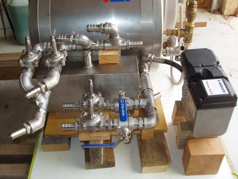
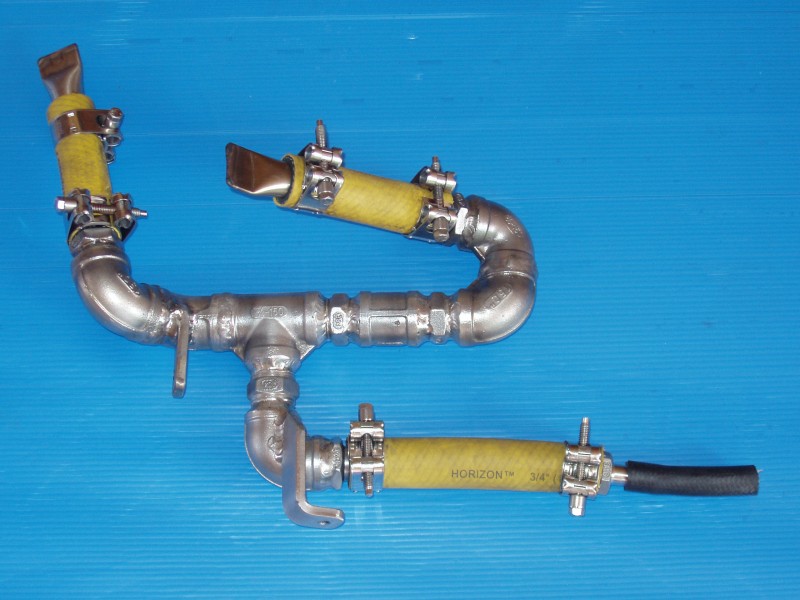
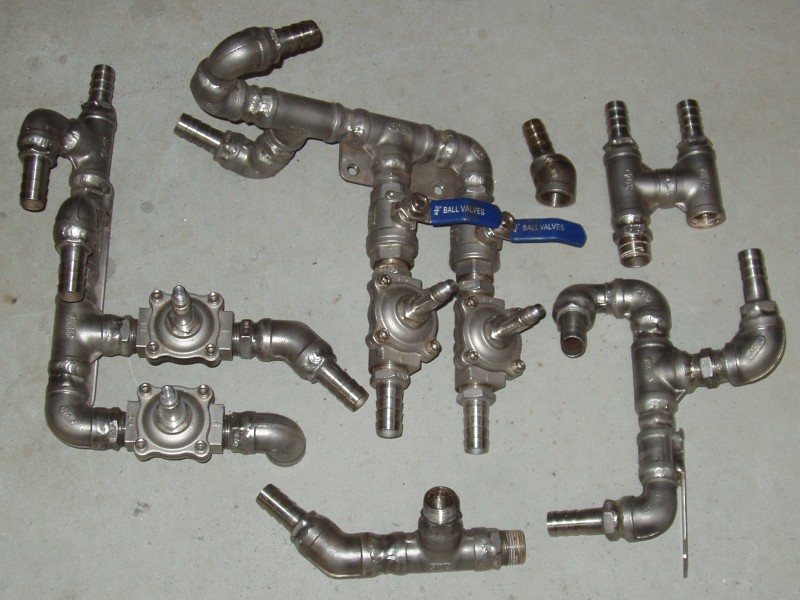
The actual plumbing design of my hydronic system utilises quite a lot of stainless steel fittings. I sourced all of my valves and fittings direct from a factory in China, simply because they were 90% cheaper than buying the equivalent equipment here in Australia. Sad, but true!
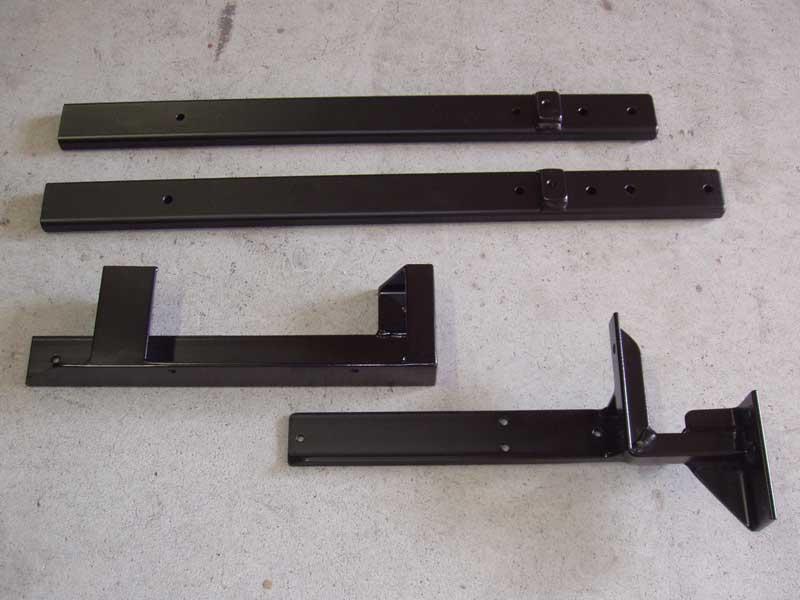
With boxes full of fittings and valves, it was time to get down to putting the plumbing together. Many a night were spent “playing Tetris”, trying to come up with a working configuration that matched the schematic and also fitted into the very limited space where it all had to go. It’s all about perseverance… you just have to keep trying until you get something that is workable. When I had I what thought was a viable solution, I did a mock-up of all the hydronic components so that I could come up with a design for the bracket needed to hold everything in place. Initially I built a one piece bracket but this proved to be problematic because removing any of the items from under the truck would have been virtually impossible. A new four piece “modular” bracket was designed to overcome this issue.
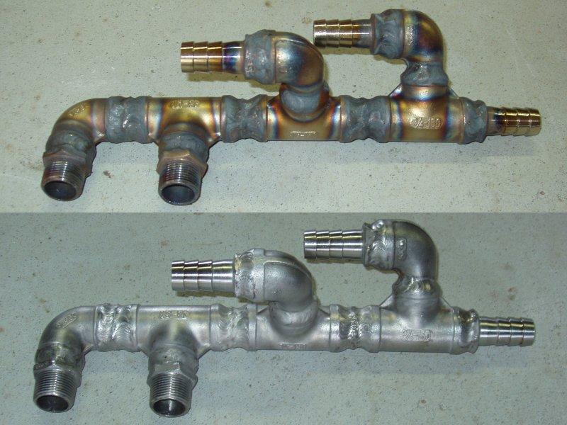
Because my plumbing is made up with numerous individual fittings I decided to weld together as many fittings as possible, which should reduce the possibility of leaks developing at those joints. Thread sealant would only be used on the valves and where necessary for assembly/disassembly reasons. For thread sealing I used Loctite Primer T to prepare the threads and Loctite 569 hydraulic sealant. All of the stainless steel welding was done with a TIG welder.

So, everything was now sorted… right? If only…
I must admit that one of the tasks I kept putting off was tapping into the truck’s cooling system. The most important consideration here was to ensure that any connection to my camper hydronic system could in no way affect the functionality of the engine cooling system.
Initially I was going to tap into the cab heater pipes behind the grill, just before they go inside the cab. However, the more I looked at that location the more issues I saw. One of the problems with this location is that you have to allow for tilting of the cab, plus it is probably the furthest point from where the hydronic system is located, meaning that longer hoses would be required. When I realised that the cab heater circuit was in itself a parallel circuit in the truck’s cooling system I decided that a series connection into my hydronic system was possible from that circuit.
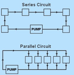 For anyone that does not know the difference between a parallel and a series circuit, let me explain…
In a series circuit, one component is connected to the next, then to the next and so on. There is only one possible flow path, that being through each individual component. The advantage of a series connection is that equal flow is guaranteed though each component, but if there is a blockage in any part of the circuit, the whole circuit ceases to function. It should be noted that in a heating system that uses a series circuit that the temperature of the coolant will be lowered as it passes through each individual component.
In a parallel circuit there are multiple flow paths. If a blockage occurs at any one component, flow will still continue through the other components. The disadvantage of a parallel circuit is that the coolant will always take the path of least restriction. This means that it is possible that flow is limited or non-existent through some components. To overcome this issue, balancing valves can be used. An advantage of parallel circuits is that it is easy to disable individual components with a shut off valve.
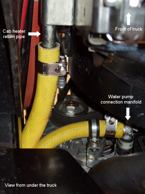
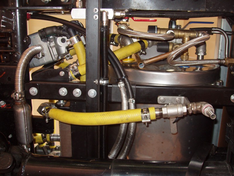
I chose to make my connection where the cab heater return line goes back into the truck’s water pump. Why I had not considered this location previously I don’t know, as connecting here turned out to be quite simple. The only real issue was that the OEM pipes/hoses are 18mm, which is not a standard hose size. I am using ¾” hose (19mm), so I needed to pad out the pipe size a little. To do this I used some dual wall heat shrink, which worked perfectly.
When I was trying to figure out exactly how I was going to route all of the pipework into the camper I determined that this was going to be an extremely difficult task with my current design. This design had four lines that needed to be run into the camper body; a flow and return line for both the cabin heater and towel rail. Basically, there just wasn’t enough room to run this many lines. Bugger!
I determined that the only real option was to run only two lines into the camper body. The unfortunate thing about this epiphany was that it meant totally redesigning all of my welded manifolds. The design was changed so that the cabin and towel rail valves would go inside the camper, opposed to where they were, between the chassis rails. I will split the single line into two in the camper and add the balance and control valves at that point. I will wait until the camper body is built before doing this part of the plumbing.
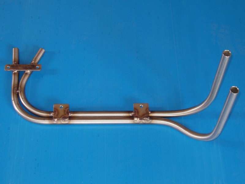
As I have said, there is very limited space to work with but there was just enough of a gap between the subframe and chassis rail to run some 19mm pipe. As you would expect, it was far more challenging bending the 19mm pipe than it was the 13mm pipe I used for my fuel system.
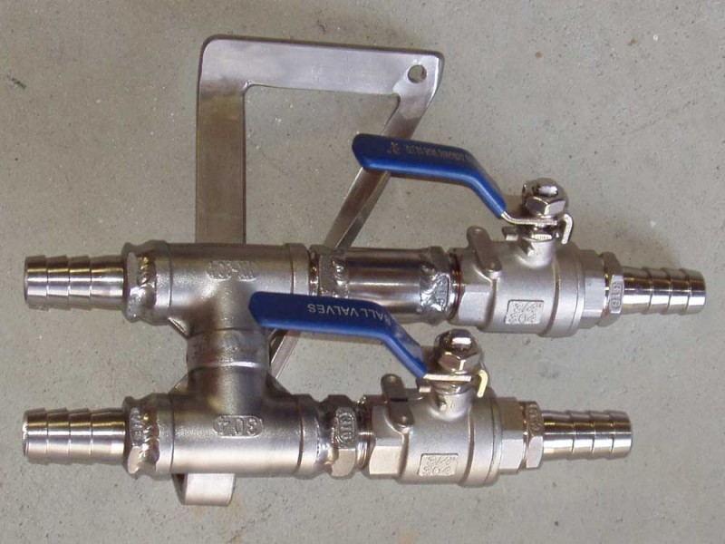
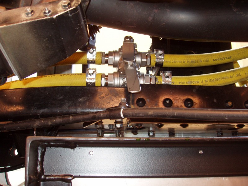
I should mention at this point that I always had some reservations about using diaphragm valves, mainly because they have more moving parts, opposed to ball valves that are very simplistic. Diaphragm valves were used because they were the only electrically operated valves I could find at the time. As it happened… I was searching online for something totally unrelated and stumbled upon motorised ball valves.
Who knew these were available? Certainly not me! Finding these valves made me happy and sad at the same time. They were ideal for my setup but it meant spending even more money on this part of the build.
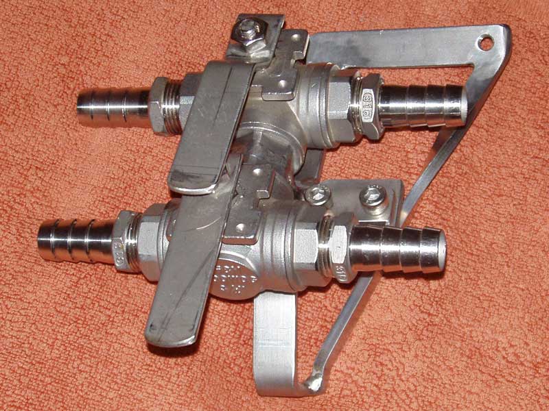
So, the decision was made to buy more stainless steel fittings and some of these motorised ball valves. When everything arrived I got to play Tetris again, but this time it was much quicker coming up with a new plumbing configuration, which was a small consolation. Unfortunately, I took some advice from a non technical person at the valve company and ended up with the wrong controllers for the valves. I could have used the ones I got, but it would have been more of a hassle than just replacing them, which is what I did. Yep… more money down the drain!

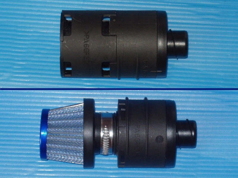
Another modification that I made was to the boiler’s air intake silencer. Upon inspection of this item I discovered that it was not actually an air filter, just something to reduce the air intake noise. Given that our truck will likely operate in dusty environments I felt that is was prudent to have some sort of air filter installed. To that end, I removed the end cover from the silencer and fitted a small diff breather. The boiler’s air intake is now filtered, which can only be a good thing.
With the boiler repositioned, new manifolds welded up and the motorised ball valves fitted, it was time to put everything in the truck (again).
After filling the system with coolant and bleeding it, the engine was started to verify that everything now worked as it should. I was happy to see that heat was going where it should go and everything was looking good, until I spotted a leak in one of my manifolds. On closer inspection I was shocked to see that the leak was coming from a micro fracture in one of the fittings. The leak was not coming from where I had welded the fitting, it was coming from the body of the fitting. After some cursing and swearing, I drained the system and removed the offending manifold so that I could weld up the crack. The joy did not end there however… I welded up the crack only to find that the fitting started leaking at another point. After three more attempts at fixing these cracks I gave up and decided that I needed to replace the offending fitting. I ascertained that there must have been a production issue with this fitting, which was a bit of a concern. Needless to say, I was definitely not impressed about having to do this, as it was an involved job. Anyway, the fitting was replaced and the manifold was reinstalled. Same procedure… fill, bleed, test. Low and behold… I found another leak in the other manifold. The leak was in the same type of 90° fitting as the other manifold. Words do not really describe what I was feeling at that point in time, but as you can probably surmise, I was not happy.
I found that the same 90° fittings in this manifold were at fault. There were two of these 90° fittings in that manifold, both of which I replaced, even though only one of them was leaking. This had definitely not been a good day for me.
On a positive note, with the defective fittings replaced on both manifolds and everything back in the truck, all was good. No leaks and I finally had a fully functioning hydronic system. Yeah!!


For those people that are interested, I should probably describe how the final version of our hydronic system actually works.
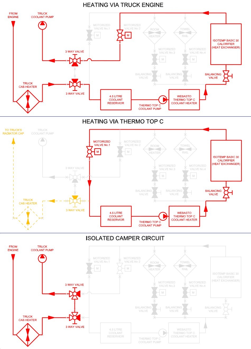
The hydronic circuit for the camper heating is hooked up using a series connection from the truck’s cab heater hose but the individual components of the hydronic system are connected in parallel. This allows the calorifier, cabin heater or heated towel rail to be turned off.
It should be noted however that at least one of these circuits needs to remain open for coolant to flow through the system; that would normally be the calorifier circuit.
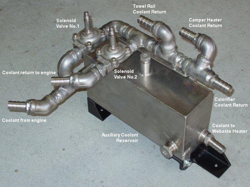
Two motorised ball valves control how the coolant flows through the hydronic system. When the truck’s engine is running, valve No.1 is closed and valve No.2 is open. In this scenario coolant will flow through the auxiliary coolant reservoir tank, the Webasto boiler and then the calorifier. Coolant will then pass through valve No.2 and back into the truck’s coolant system (directly back to the truck’s water pump).
When the truck’s engine is not running, coolant can be heated by means of the Webasto Thermo Top C diesel powered boiler, which in turn will heat the water in the calorifier and also enable the cabin heater and towel rail to function. In this scenario, the operation of the valves are reversed; valve No.1 is open and valve No.2 is closed, which creates a semi-closed loop system. According to the Webasto specifications, the boiler requires a minimum of 3 litres of coolant for optimal performance, which is why the system includes the auxiliary coolant reservoir. The Webasto boiler has it’s own circulation pump, which is used to move coolant through the camper’s heating system. Heated coolant from the Webasto boiler goes into a distribution manifold where it is directed through the calorifier and, if either of the heater valves are open (valves 3 and 4), coolant will also be allowed to flow through either, or both, of the cabin heating circuits.
As I mentioned above, by design the camper’s heating circuit is a semi-closed loop system. If for any reason an over temperature problem develops, the truck’s radiator cap will act as a pressure relief valve. Even though there is a flow path to the truck’s cooling system, coolant should not normally take this path unless there is a build-up of pressure in the system; it will flow through the camper’s heating system because this is the path of least resistance.
Another option with this system, but one that I am unlikely to use, is if valve No.1 is closed and valve No.2 is open when the engine is not running and the Webasto boiler is being used to heat the coolant. In this scenario the Webasto boiler will provide engine pre-heating, because coolant will be circulated through the trucks cooling system.
Well, there you have it…
We all make mistakes and, as is obvious from what I have written here, I am definitely not exempt from this.
Sometimes shit happens; you just have to deal with it and move on.