 Click any image to enlarge
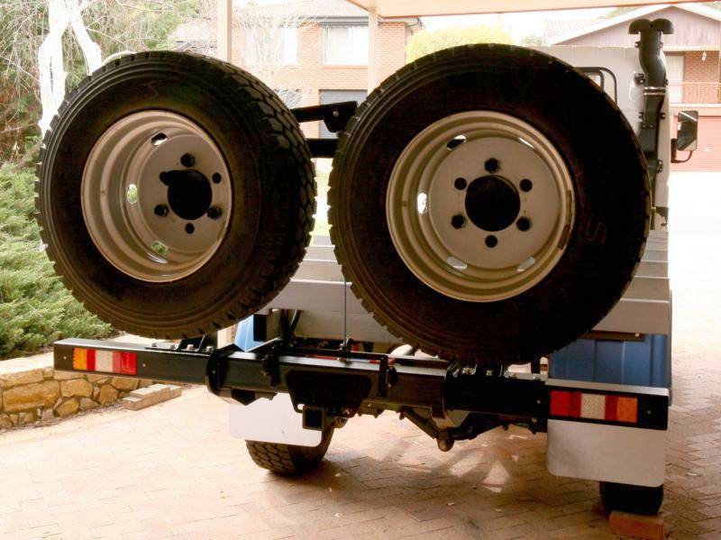
I have two spare wheels that need to be mounted on the rear of my truck. These wheels are not light, weighing in at around 80Kg each, so a fairly robust setup is required if the wheel carriers are to withstand the rigours of off road travel. Given the weight of the wheels, a lifting and lowering system will also be required.
I tend to preference strength over weight when designing pretty much all of the equipment for this expedition camper. Weight is definitely taken into consideration, but I do not focus on it, as I know some other people do. The total weight for the rear bar and tyre carrier will be just under100Kg, but I do not consider this to be excessive, given the task it is being designed for.
The starting point for this part of the project was to draw up all of the rear bar components in AutoCAD.

One of the primary reasons for using AutoCAD is that I needed to get some of the parts laser cut. Providing my own DXF files greatly reduced the cost of getting these parts cut, as I was not paying for someone else’s time to draw them up.
I chose to use Larsen Engineering in Wodonga again to do my cutting, as they consistently give me a good price.
The parts I had cut were a variety of 8mm, 10mm and 12mm mild steel plate and these were delivered to my door in the same week in which I placed the order. You cannot complain with that service.
The basic design consists of the following:
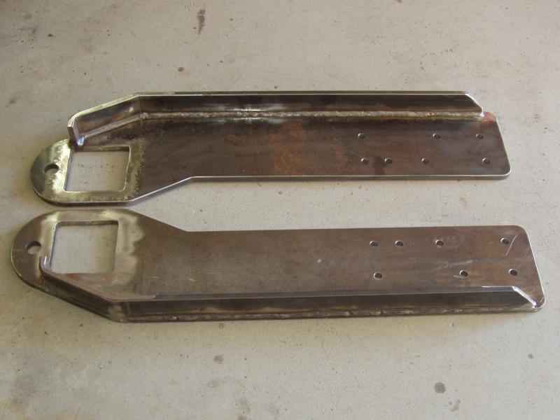
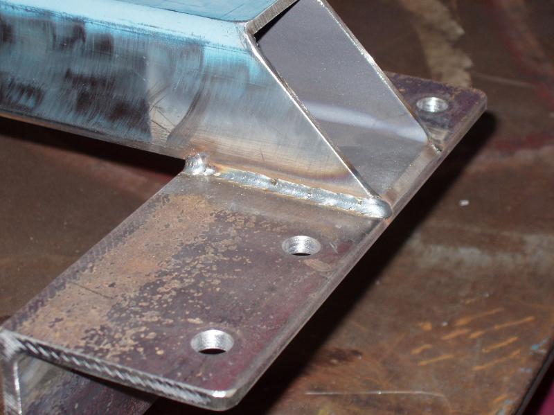
- 12mm thick “arms” that connect the rear bar to the chassis rails, reinforced for additional lateral support.
- 100mm x 100mm x 4mm SHS for the main rear bar.
- 65mm x 65mm x 4mm SHS for the tyre support uprights and cross beam.
- 10mm x 300mm diameter discs for the tyre mounts.
- Outer wheel studs and nuts, recycled from the dual wheels, for attaching the spare wheels.
- Assorted 8mm mounting and bracing pieces.
- Hayman Reese style receiver.
- Runva 3.5P ATV winch, which is used to lift and lower the wheels.
- Swing out crane arm.
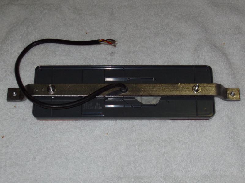
- ADR approved LED tail and number plate lights.
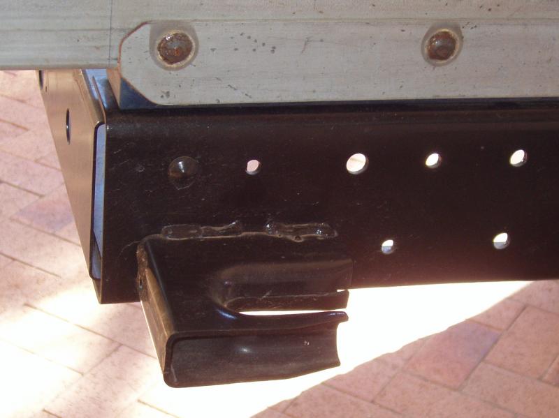
The first job was to remove the rivets from the rear chassis cross member. This was necessary in order to mount the two rear bar support arms to the side of the chassis rails. This cross member is secured to the chassis rails with four rivets, all of which had to be drilled out. The bottom rivet, on the driver’s side, is obscured by a recovery hook, so this had to be removed in order to get to that rivet. The rear cross member will also be replaced by a more sturdy version, to give the rear of the chassis a little more strength. It will also serve as one of the mount points for the tyre lifting/lowering winch.
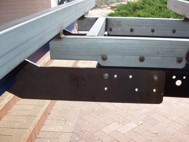


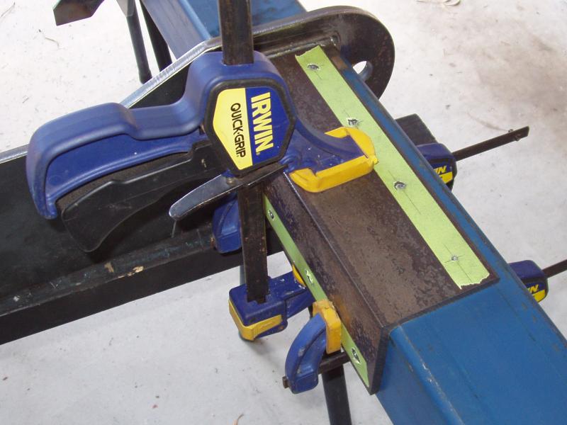
Holes were drilled into the rear bar support arms that matched existing holes in the chassis rails, then the rear bar was “test fitted”.
The rear bar support arms were then removed from the truck and prepared for welding of the lateral support strengthening bars. This involved filleting and removal of mill scale in all areas to be welded.


I have no intentions, at this point in time, to tow anything behind the truck but it seemed only logical that when building the rear bar that it should include a towing hitch.
I built a Hayman Reese style receiver, which is made from 65mm x 65mm x 6mm SHS with a 75mm x 75mm x 5mm collar at the end for additional strength. The flanges at the rear of the hitch are used to secure the wheel lifting/lowering winch mount.
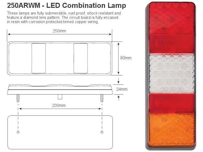
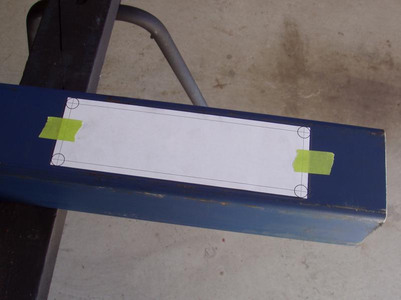
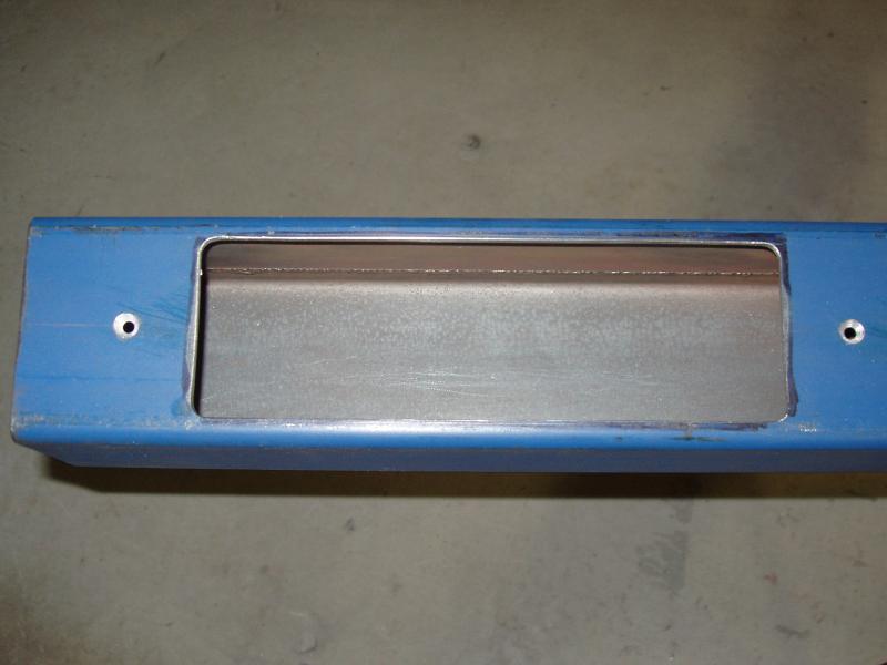
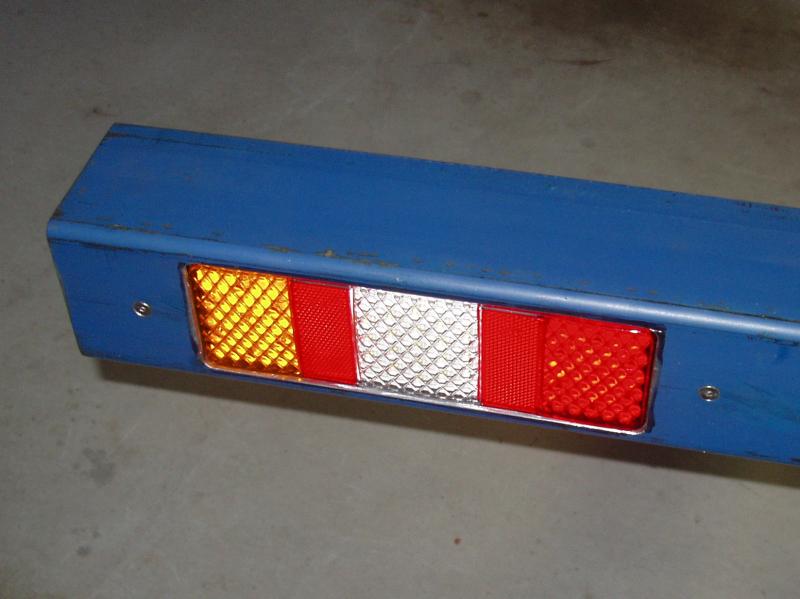
I was going to use the OEM rear lights but chose to buy some new LED lights instead. I cut holes at either end of the bar so that the lights could be flush mounted. I also made some stepped brackets so that the lights could be mounted from the front.
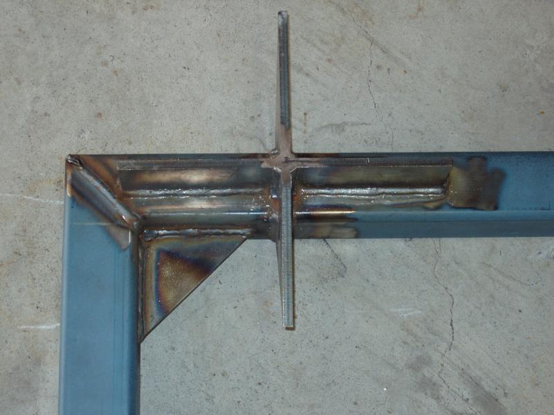
My initial design for the spare wheel carriers was to weld the upright bars directly onto the main rear bar, but after some deliberation I decided that it would be technically better if the upright bars were bolted to the main rear bar instead. Using bolts allows for more flexing, which should make the spare wheel carriers more robust. The downside was that this design would be slightly heavier, as more material had to be used.
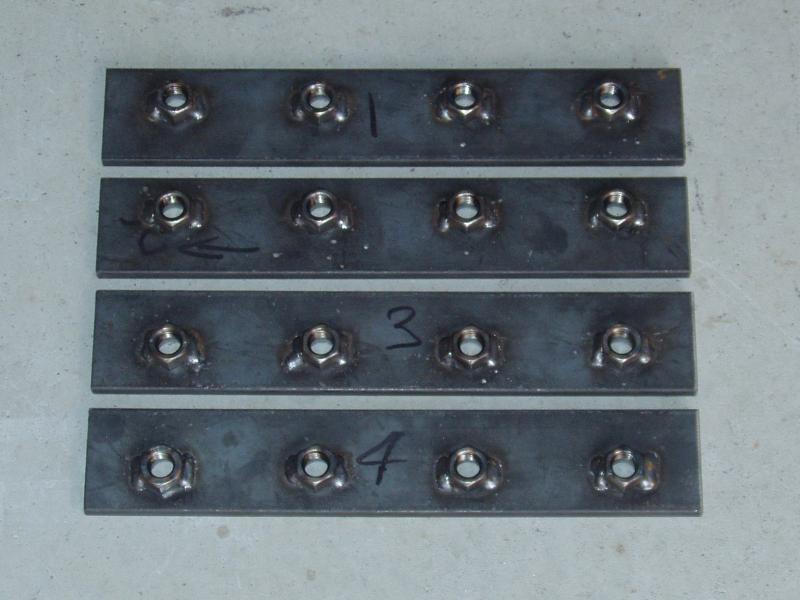
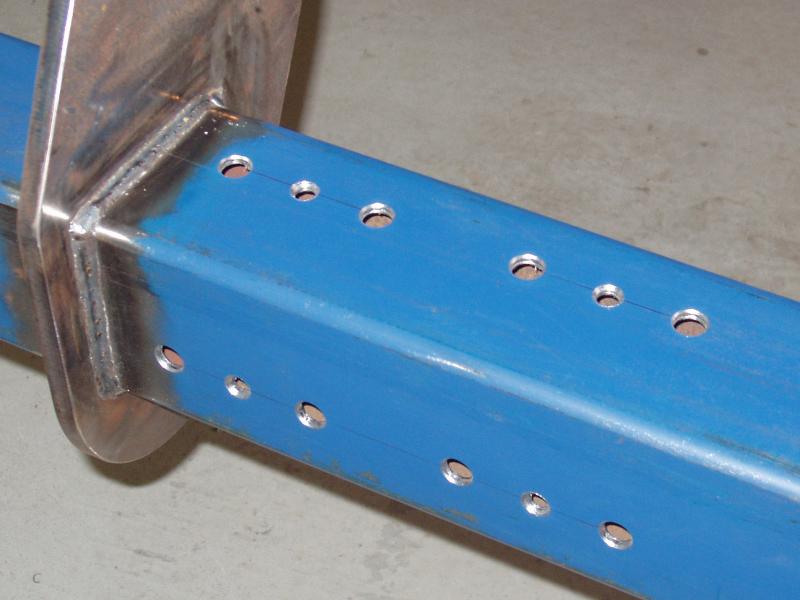
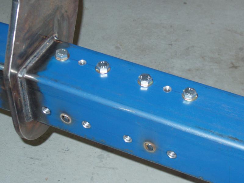

The main mounts for the uprights use 90mm x 8mm thick structural angle along with 50mm x 8mm flat bar for mounting the nuts. Eight M12 bolts secure each piece of angle to the main bar; four on the top and four at the rear. M12 nuts are welded to the 50mm flat bar and the bar is plug welded to the main rear bar, holding it in place. This technique gives additional support to the mounts by spreading the load more evenly along the rear bar. Another advantage of using this approach is that if the worst happens, and a weld does fracture on either of the spare wheel carriers, the spare wheel carrier assembly can be removed for repair without having to remove the entire rear bar.
As previously noted, the rim and tyre configuration that I have weighs in at about 80Kg per wheel.
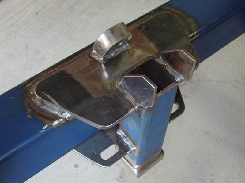
This is far in excess of what I could lift up onto the spare wheel carrier by myself, so a winching system was developed to lift the wheels up onto the spare wheel carriers. The lifting system involves a crane arm, some pulleys and a small ATV winch. The lower pulley is attached to the rear of the main bar and is designed to swivel, which allows for the spooling of the winch.
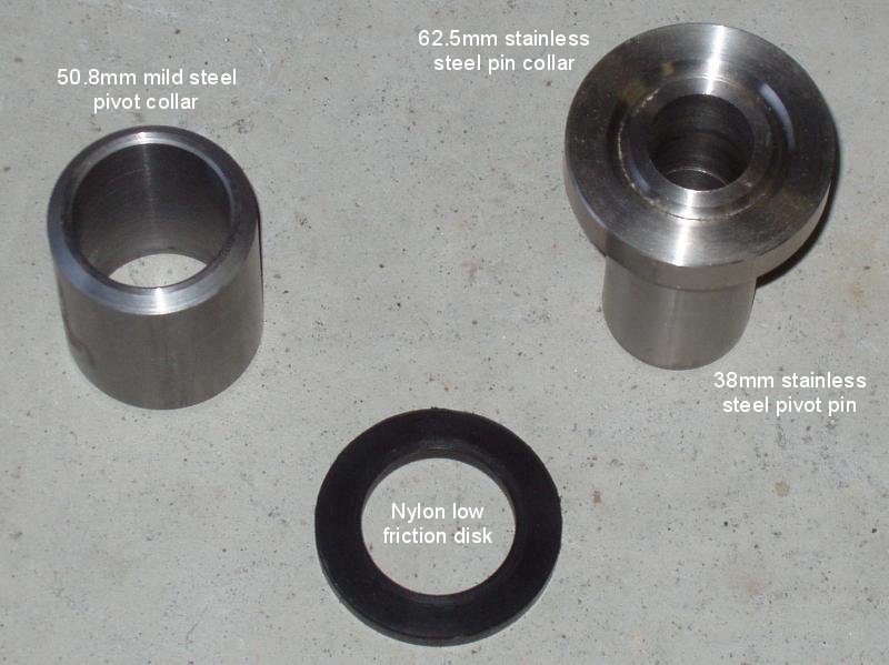
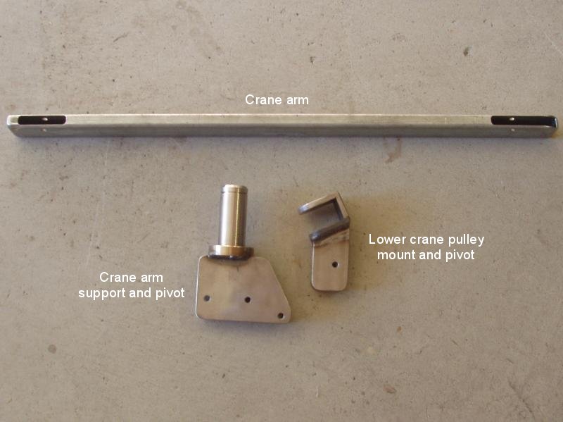
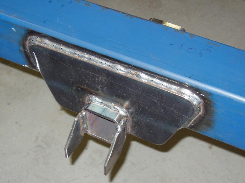
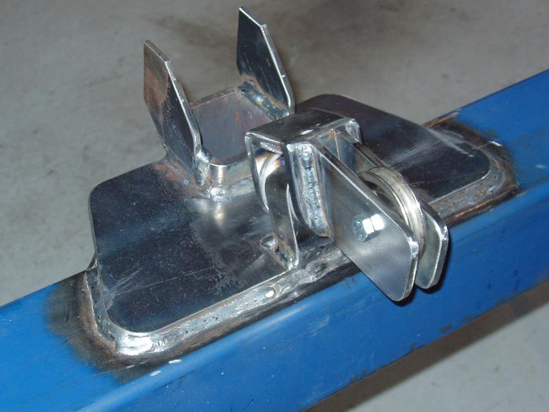
The pivot for the crane arm consists of a stainless steel hollow pin that is fitted into a mild steel sleeve.
The pivot pin was made from a piece of solid 38mm bar. A 29mm hole was bored through the centre, which is large enough for the thimble on the winch cable to pass through. On the top of the pivot pin is a 62.5mm stainless steel collar. The pivot pin was press fit into the collar then welded to permanently secure it into position. Two flanges were welded onto the top of the collar to house the crane arm.
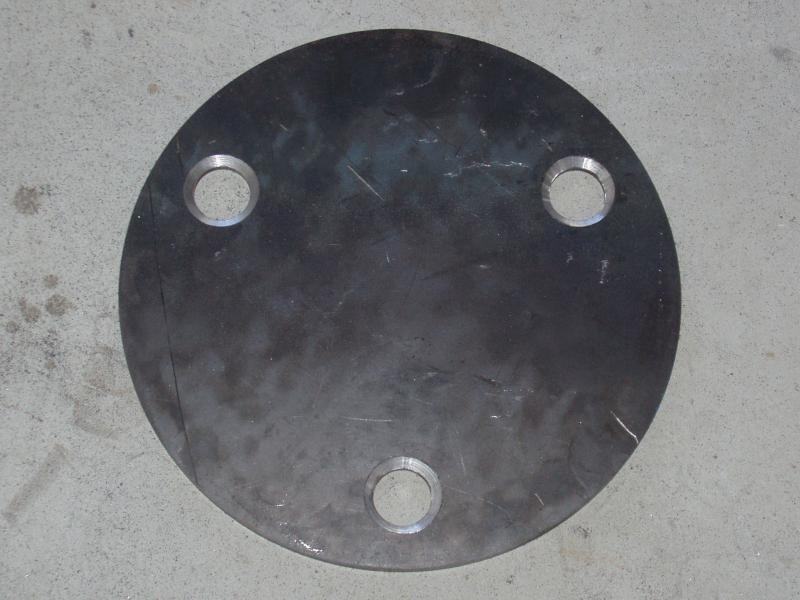
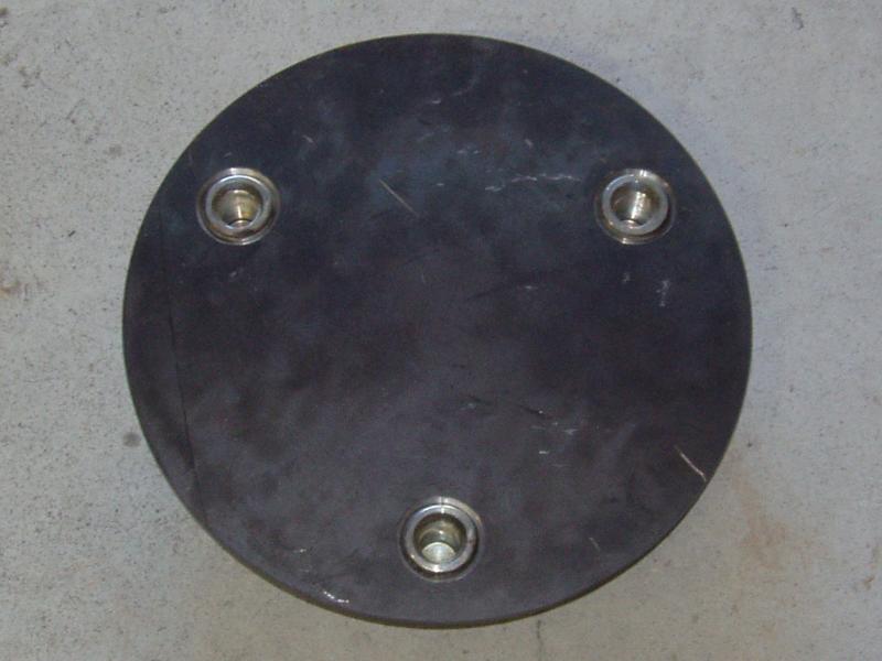
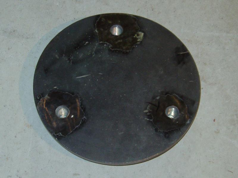
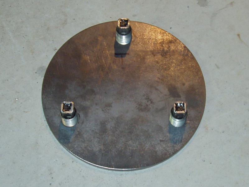
Each spare wheel is secured to its own tyre carrier with three 30mm wheel studs that are mounted on a 300mm x 10mm thick disk.
The original outer wheel studs, used to secure the outer wheels of the dual wheels, were recycled for this purpose. The 30mm holes were laser cut, not drilled. I chose to take the disks to an engineering company to get the holes countersunk, as this was a much cheaper option than buying a 40mm countersink bit. The reason for getting them countersunk was to provide a fillet for welding on the wheel studs. Although it was not really necessary, I ground back these welds, ’cause it looked better.
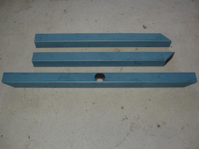
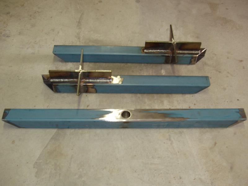
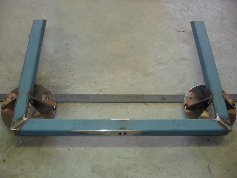
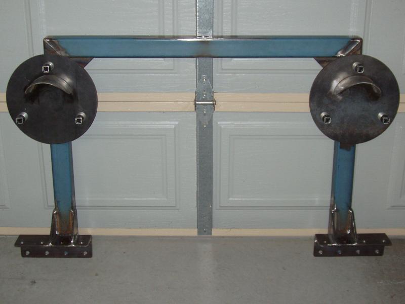
The basic structure of the wheel carrier consists of two uprights, that hold the spare wheel support disks, and a cross member, which adds some lateral support and holds the lifting crane. These pieces are made from 4mm thick 65mm SHS tubing.
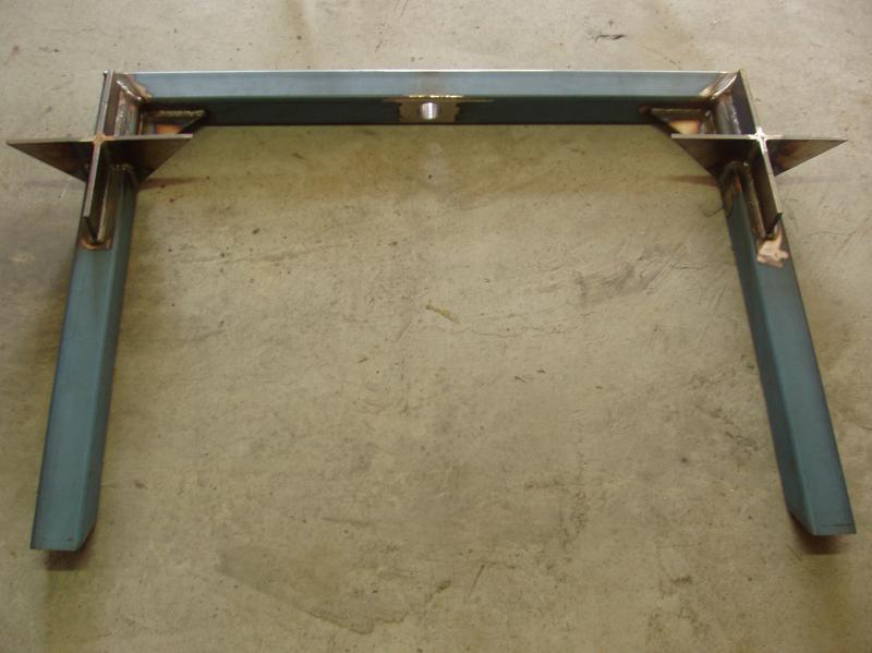
A hole was drilled in the centre of the cross member and the mild steel sleeve for the crane pivot was welded into it. The welds needed to be ground flush, as the surface needed to be flat for the low friction crane pivot bearing. The spare wheel disc support brackets were welded to each upright, then the two uprights were welded to the cross member. Support gussets were welded in each corner to add additional strength. With the basic frame constructed, the spare wheel discs were aligned by using a piece of flat bar against the lower wheel studs. The discs were tack welded in place, checked for alignment, then fully welded. Wheel supports, used as a safety device when fitting the wheels to the carriers, were welded to the front of each disc.
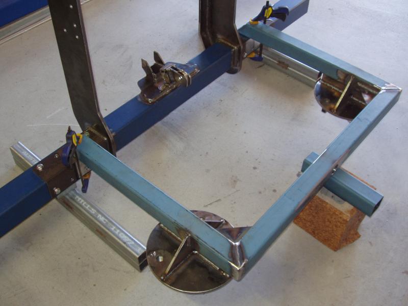
The spare wheel carrier frame was positioned with the main rear bar and the 90mm angle pieces, ensuring that everything was aligned correctly. A small root weld was made while everything was clamped together, then the frame was removed from the rear bar. Additional braces were then welded to each side of both uprights. The purpose of these braces is to increase fore/aft stability and the strength of the welded joints.

To comply with ADR requirements, the number plate must be visible at 45° from either side of the truck and 45° from above.
Initially I was going to mount the number plate on top of the rear bar and as close to the back as possible. When I fitted the spare wheels to the tyre carrier I quickly realised that the tyres would obscure the number plate if I positioned it there. After a bit of a rethink I decided that the only place I could really put the number plate was directly above the hitch. To that end, I made a frame for the number plate from 20mm x 3mm angle that positioned it there.
With the fabrication and welding completed the bar was taken to a local engineering company where it was sand blasted, zinc coated and powder coated. I am not a big fan of powder coating but decided to go down this route in order to match the rear bar with the bullbar, which was done in a satin ripple black finish by the same company. When I got the bar back I fitted it to the truck and installed the tyre lifting winch.
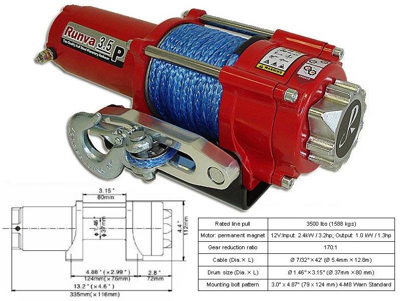

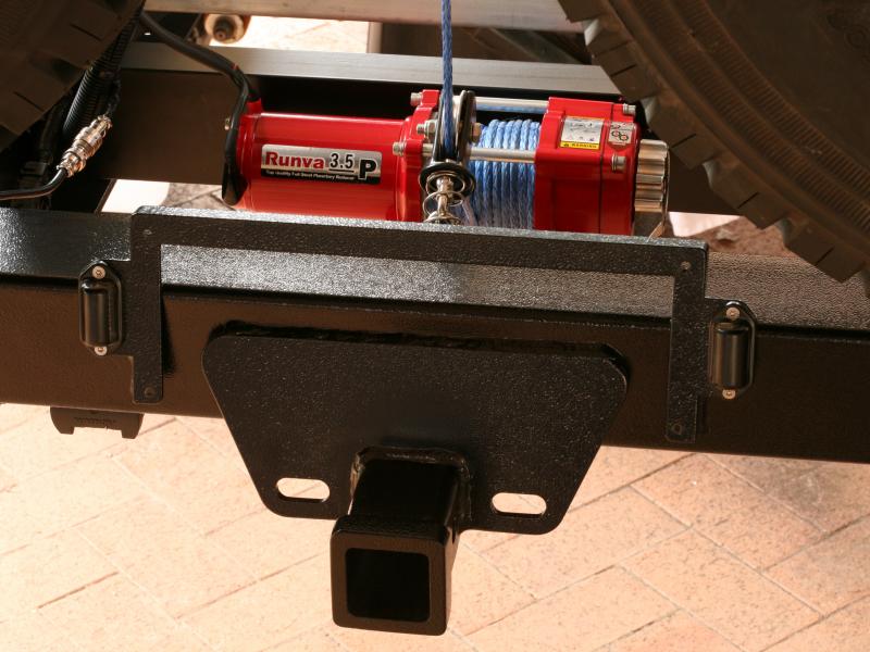
To lift/lower the spare wheels from the wheel carrier I have chosen to use a Runva 3.5P ATV winch. This is serious overkill for the task, but many of the other small winches I looked at were just nasty. I wanted something that I knew would be reliable and easy to use, and this winch pretty much fit that requirement. The winch is mounted on two sections of 40mm x 5mm angle, attached to the rear cross member at one end and to the lugs at the rear of the receiver at the other end.
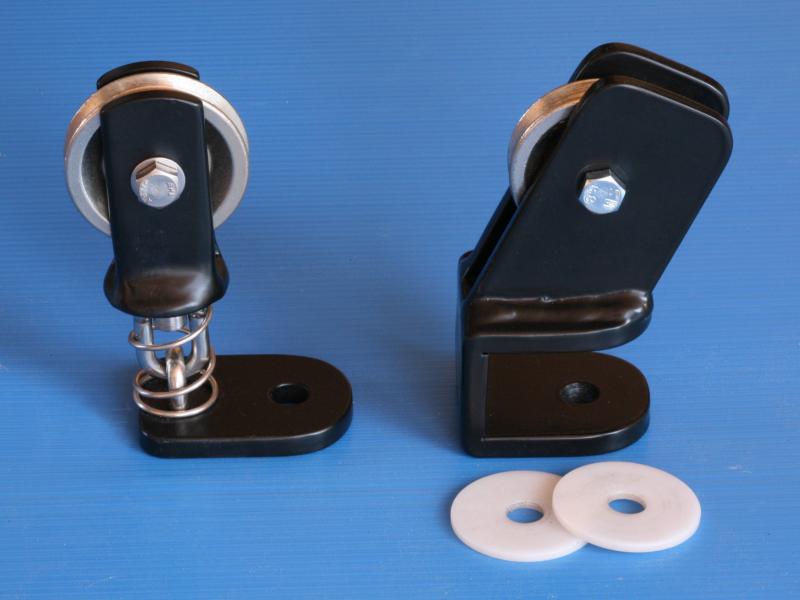

I spent quite a bit of time and effort designing and making the lower pivot for the tyre lifting cable, but when I tested everything this pivot didn’t actually pivot when under load.
Bugger! The design I have now is a copy of a marine stand up swivel block. I made my own because I could not find one that had a removable pulley. A removable pulley allows me to feed the rope into the pulley block without spooling all of the rope off the drum.
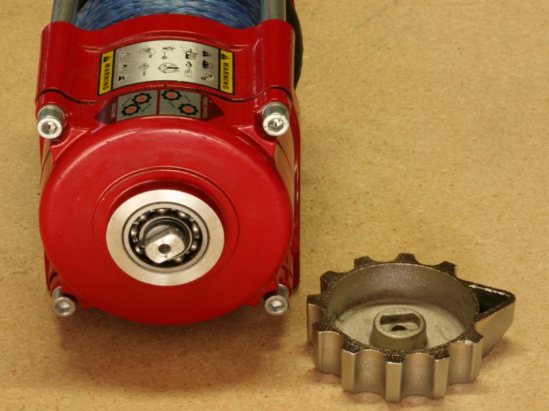
Contrary to what is stated on the Runva website, this winch is not what I would call “extremely watertight”.
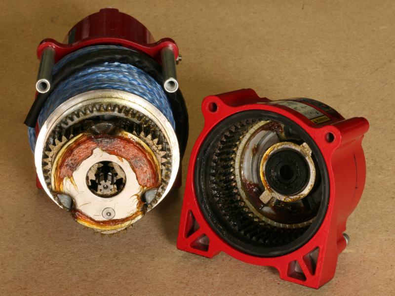
The motor itself is quite well sealed, having O rings on the securing bolts and a sealed bearing at the drive end. However, the gearbox end of the winch has no actual seals whatsoever. At the drum side of the gearbox, sealing is accomplished only by the grease between the drum and the gearbox bush and on the clutch side of the gearbox there is an open bearing, which has virtually no protection against water or dust.
The rear of the truck, where the winch is located, will likely be subjected to high dust levels, due to the vortex action that occurs in that area.
This winch is a critical item; without it, changing the wheels would be extremely difficult, if not impossible. If dust was able to get into the gearbox bearing it is likely that it would result in the bearing seizing, making the winch unusable. That would be a very undesirable scenario.
For this reason I have elected to replace the open bearing with a sealed one (16002 2RS). I cannot understand why Runva do not do this.
I still think that this is a decent winch; if I didn’t then I definitely would not have installed it as one of my critical systems.
The point I am trying to highlight here is that you shouldn’t always believe what you read. Sometimes it is beneficial to pull things apart in order to verify it’s fit for purpose. It’s definitely better to know this prior to installing equipment, opposed to finding out it wasn’t when it fails.
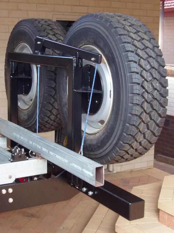
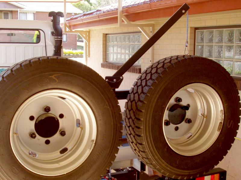
Using the winch it is relatively simple to lift the spare wheels onto or off the tyre carrier.
To lift the wheels the crane arm is raised to approximately 45° and it is locked into place with two stainless steel pins. A tie down strap is run through the rim and, via a spring clip, it is attached to the thimble on the winch rope. Even with all of the wheel nuts removed, the spare wheel sits quite safely on the carrier because of the wheel support bracket.
Wiring everything up…
I decided that using a dedicated isolator for the tyre lifting winch would not have any real benefit. Instead, I utilised the isolator for the main recovery winch, figuring that I would never be using the two winches at the same time. The cable run from the truck batteries to the winch solenoid is approximately 4.5 metres. I used 6B&S cable (15mm²), even though voltage drop is a not really a factor with this installation.
The winch solenoid is bolted onto the subframe rail and a short length of cable connects the winch to the solenoid. The winch controller cable/plug is easily accessible from the rear of the truck, but I decided to add a wireless receiver for this winch, for the simple reason that it just makes it easier. I bought this controller, which came with a key fob remote, off eBay for about eleven bucks (delivered).

The remote was of a much higher quality than I had expected, so I ordered a second controller and remote in order to have a spare remote. After all, they cost virtually nothing. One thing to note here is that these controllers and remotes use a fixed security code and are paired to each other, so the remotes are not interchangeable with the controllers. Well, that’s true if you don’t know how to change the security code…
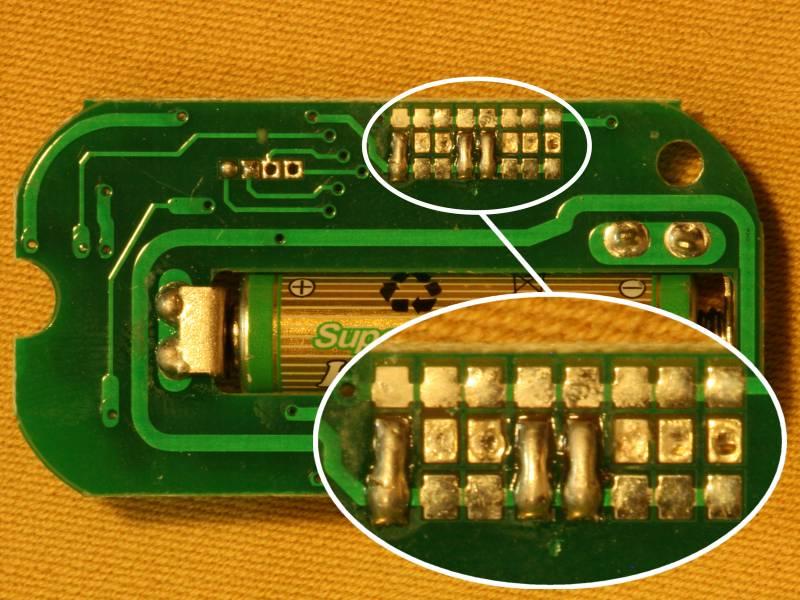
On this particular remote, if you open it up and remove the circuit board you will see a series of connections on the rear of the board, some of which will have solder bridges. How those solder bridges are configured dictates the security code that is allocated to that remote/controller pair. You don’t need to know the security code the remote uses, all you need to do is match the solder bridges on one of the remotes with your other remote. This gave me two remotes for the one controller. 
I can’t take the credit for knowing all this kind of stuff. Thanks must go to Simon, who is my electronics guru when it comes to these matters.
The OEM wiring harness for the rear lights contained multiple plugs, only one of which (reversing beeper) was going to be utilised in this new rear bar installation. The wiring harness was cut, just behind the differential, and a new “streamlined” loom was created. Seven wires are required for the rear lights in this truck (earth, left and right indicators, left and right tail/number plate, reverse/reversing beeper and brake).
One additional wire was also included for an electronic trailer brake controller, even though I have no intention of utilising this currently. This wire is only run to the seven pin trailer plug, not into the rear bar. A length of seven core trailer wire was run into the inside of the rear bar and this was then made into a hard wired loom that connected all of the lights. LED lights are fairly reliable, so I was not really concerned about hard wiring these lights directly into the loom. Behind the rear chassis cross member there are two four pin waterproof plugs that allow for the disconnection of the wiring harness, should it be necessary to remove the rear bar.
Making new wiring looms inevitably involves quite a few electrical connections and joins. What’s the best way to do these?
Some people may argue that all auto electrical connections should be crimped, not soldered; I do not entirely agree with this.
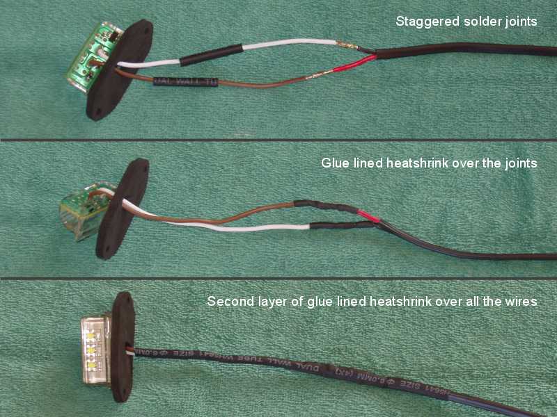
When it comes to terminal connections, soldering is definitely not ideal, as it can make the joint brittle and this can lead to breakage if the connector is subjected to a lot of vibration or movement. In my opinion, all terminal connections should be crimped. Connections in a loom however, I prefer to solder those. Wherever possible, all joins should be staggered, be they crimped or soldered. This reduces the possibility of any short circuits occurring where there is more than one connection. Heat shrink is a better insulation option than electrical tape, and glue lined heat shrink, normally referred to as dual wall, is even better. Glue lined heat shrink will also improve the IP rating and strengthen the area where it is applied, which helps to stabilise the joint.
With the use of the truck’s wiring diagram and a multimeter everything was hooked up and functioned as designed.
Split corrugated tubing was also used on all cabling to give an additional level of wear protection, not that it was really needed.
Job done!