 Click any image to enlarge
Right from the onset I knew that the Fuso’s OEM diesel fuel tank would not meet my requirements and would need upgrading.
The general “rule of thumb” for four wheel driving in Australia is that you should have enough fuel to do a minimum of 1000 kilometres.
Working on a fuel consumption of 18L/100 kilometres, which is about average for this truck, that requires a minimum fuel capacity of 180 litres.
Many people elect to fit a second OEM fuel tank, normally on the opposite side, to increase the fuel carrying capacity.
I too could have done this, but here is why I didn’t:
- A side mounted fuel tank creates torsional loads on the chassis.
The standard fuel tank hangs off the side of the chassis rail and this is known to cause fractures in the cross members, especially if the truck is used in off-road environments. - A second tank would require balancing plumbing.
If you do not keep the tanks balanced then the weight distribution is affected significantly. - A tank on either side complicates filling.
The fuel fillers would be on opposite sides of the truck.
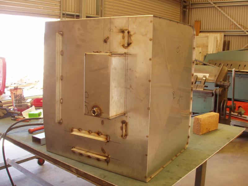
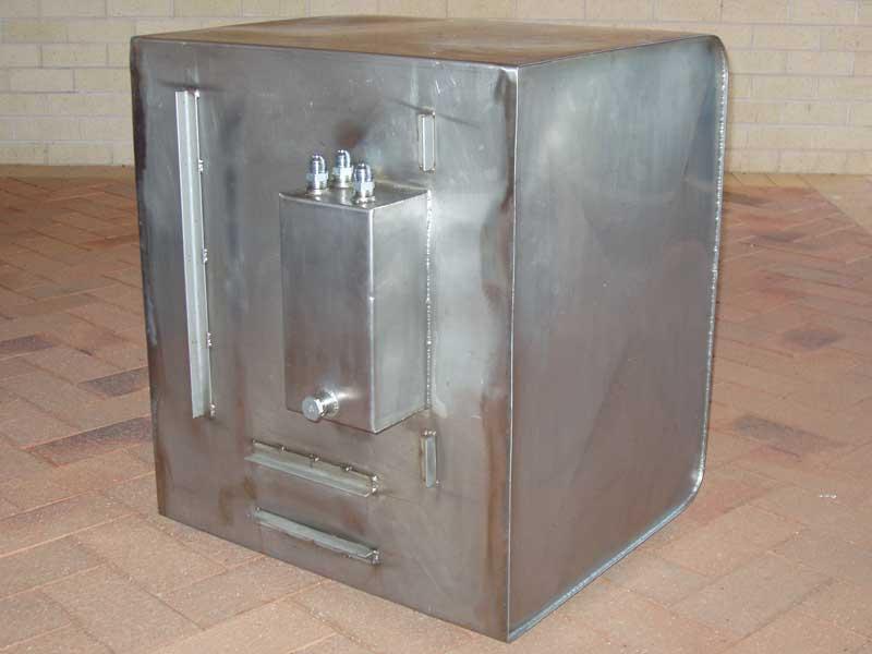
My solution was to remove the OEM fuel tank completely and centrally mount my new fuel tank between the chassis rails.
In my opinion, this was the best way to mount a large fuel tank, but it definitely proved to be more complicated than I had thought it would be.
Fitting a 200 litre tank between the chassis rails was not the problem, in fact, that part was quite easy. Getting fuel into the tank however… that was much more of a technical challenge. Unfortunately, that was not something I anticipated when designing the subframe. Oops!
Initially I had intended to get an aluminium tank made in Sydney by Shawn’s Custom Alloy. The original quote I got was for $800-$1000, which was reasonable, but after I had met with Shawn (for the second time) and supplied the drawings I received a quote for $2500, which was simply ridiculous. This threw my plans and time frame into the toilet; I now had to start my search again for another fuel tank manufacturer.
A friend gave me the contact details for Vincenc & Bridgeford, a stainless steel fabrication company in Queanbeyan, which is only 30Km away. I went and had a chat to them and was happy to find out that the sheetmetal fabricator/welder was friendly, highly skilled and certified for pressure vessels. I gave them my drawings and got a quote for $1300 for a tank made from 1.6mm 316 stainless steel sheet. A custom made stainless steel tank for half the price quoted for an equivalent aluminium tank; have to be happy about that. The only problem was that, due to their current workload, it would be six weeks before they could start work on the tank. This was obviously not ideal, but some things are just not within your control.
I just wish I had known about Vincenc & Bridgeford before totally wasting my time and effort with Shawn’s Custom Alloy. You live and learn…

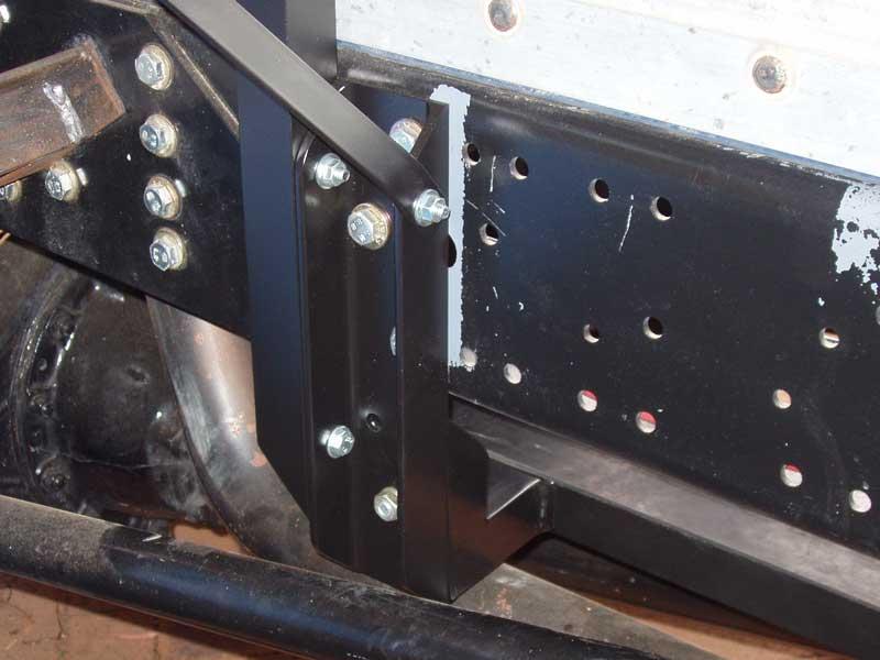
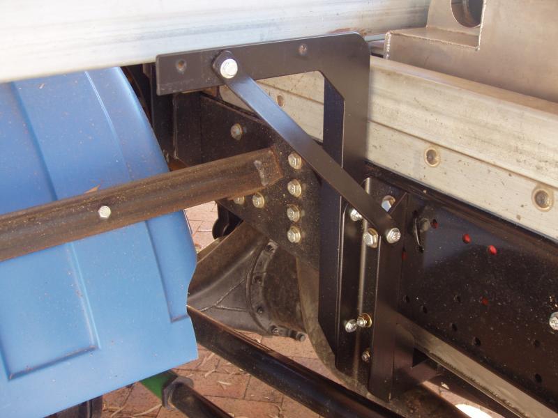
Having discussed fuel tank mounting options with numerous people I decided not to rely heavily on tank straps to support the weight of the tank. Instead I manufactured a very sturdy frame, made from 75mm C channel, for the tank to sit on. The tank support frame is bolted to the chassis rails, just like the spring mount brackets. On the underside of the tank there are locating brackets which provide lateral/fore/aft support. The tank straps simply secure the tank to the support frame, they do not really carry any load.
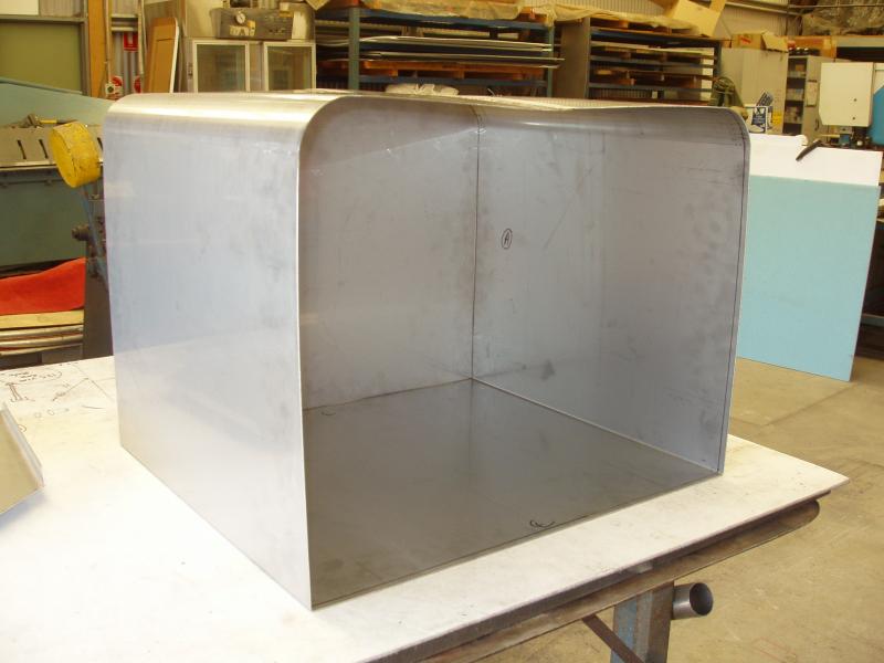
The design of the tank is quite straight forward.
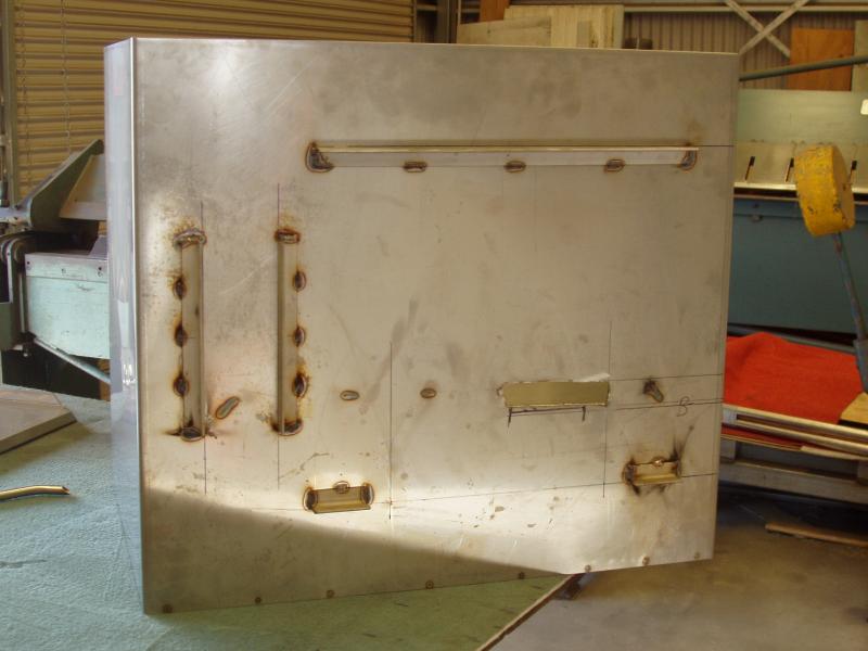
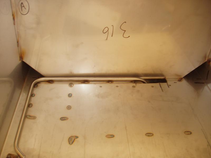
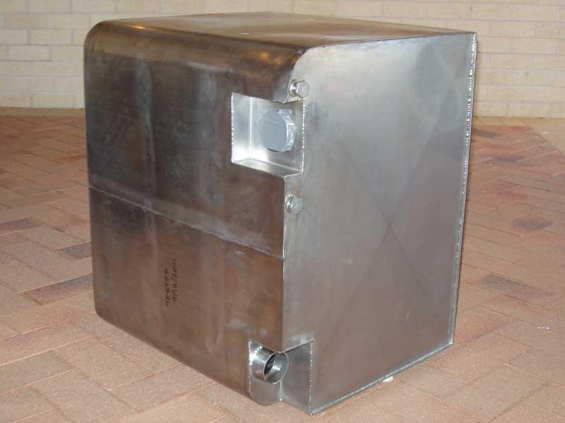
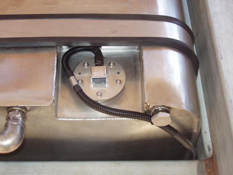
It is basically rectangular, with two rounded ends (for the tank straps) and a couple of recesses for fittings (fuel filler hose and sender unit). I also added a small sump, which is where the fuel pickups and return line are located. Two baffles run along the length of the tank and the sump acts as a third baffle.
The major advantage of getting the tank made locally was that we could do some test fitting in the truck prior to welding everything up. This proved very beneficial, as I changed a few dimensions as we progressed with the tank build.

I wanted to retain the existing fuel gauge, but in order to do this I would need a fuel sender with a 500mm range (the depth of my new tank).
I would have been happy to buy a new sender, but I was unable to find one with the correct reach and ohm range. Given I had no real alternative, the only other option was to modify the OEM sender to work with my new tank. The original sender body and float were retained and I made a new rod, using stainless steel wire, with the correct length.
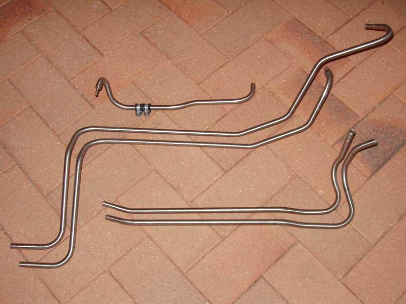
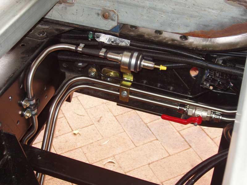
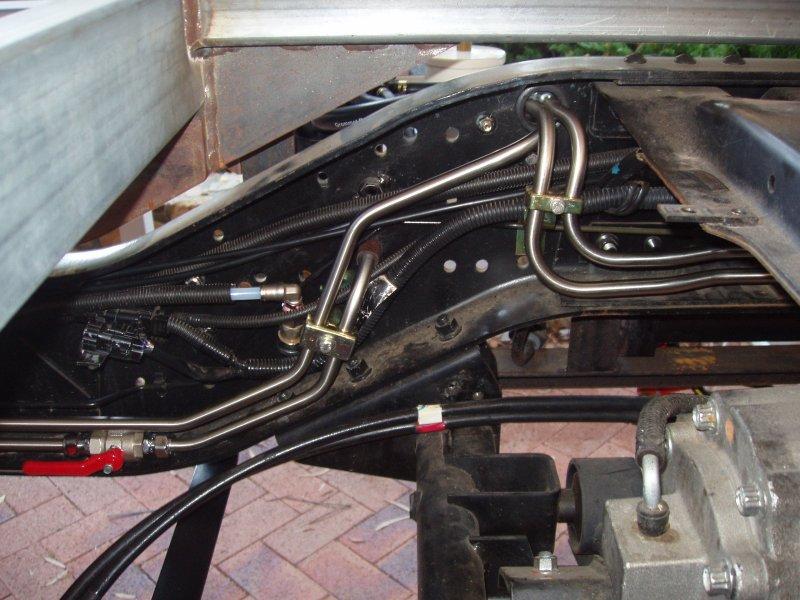
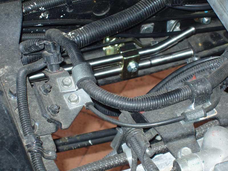
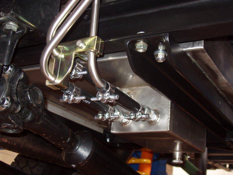
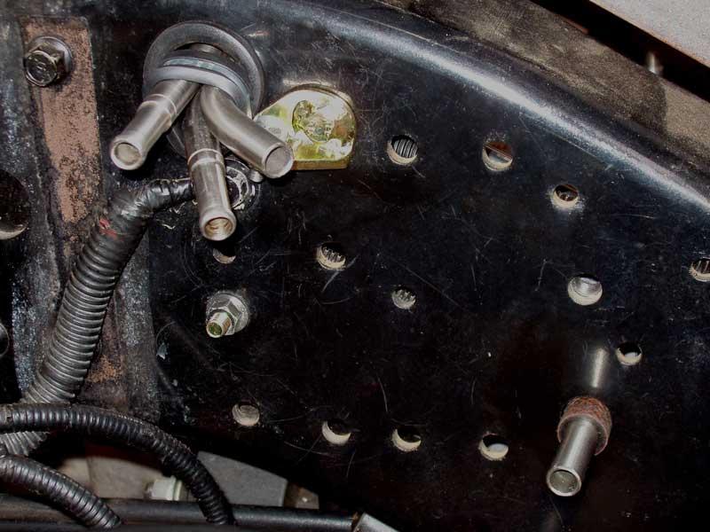
The OEM tank was plumbed with a combination of steel piping and flexible fuel hose. I wanted to use the same setup for my new tank but sourcing 12mm and 10mm steel fuel pipe proved elusive. I was going to use flexible fuel hose throughout, but that proved problematic when trying to route the lines where they needed to go. In the end I decided to do all of the fuel plumbing with 12.7mm x 1.5mm wall stainless steel tubing, as this allowed me to route all the pipework through existing holes in the chassis.
To connect to the existing fittings on the OEM fuel filter I needed to machine up some 10mm reducing nipples for the return line fittings. I also made a 5mm reducing nipple for connecting directly to the Webasto Thermo Top heater. These nipples were silver brazed into the tubing.
The biggest challenge with using stainless steel tubing is bending it. Luckily I have an old, but very good, Rigid pipe bender. I have had previous experience doing pipe fitting, which definitely helped, but I still made a few stuff ups doing the compound bends required. A bit of pipe got wasted, but in the end I was very happy with the final result.
Short lengths of fuel hose were used to connect the stainless pipe to the tank, via JIC connectors. Longer lengths of fuel hose were used to connect the filters, which allows for sufficient movement when the chassis flexes.
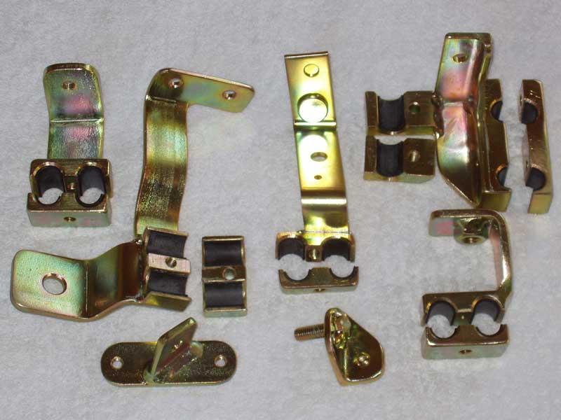
To secure all of the pipework it was necessary to manufacture a variety of custom brackets. These were all zinc plated when completed.
The big issue… getting fuel into the tank.
There is only 120mm clearance between the top of the lower subframe rail and the top of the subframe, which is not a lot of room to work with. The fuel tank has 20mm clearance on all sides, including the top; that brings it down to 100mm. The filler tube is 63mm in diameter (2½”), leaving 37mm. Add another 5mm for the thickness of the connecting hose and that leaves just over 30mm for subframe travel.
The majority of the chassis twist occurs near the chassis step and decreases significantly as you move towards the rear. My spring mounted subframe design allows for a maximum of 40mm of movement at any mount point, but given the location of the filler tube, I do not anticipate any more than 20mm of movement at that point.
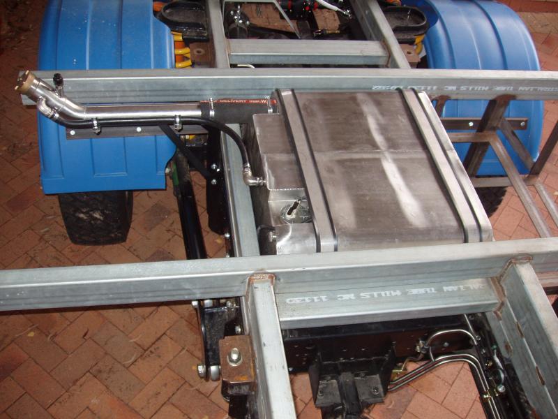
The filler tube has its own bracket which is connected to the side of the tank bracket. The tank and filler tube are connected via a short length of flexible fuel delivery hose. Should the chassis twist more than anticipated the flexible hose should allow for additional movement, as the hose can be squashed without doing any damage to the filler tube or tank filler spigot. I do not expect this to happen, but having a flexible section is a simple safety feature to include.
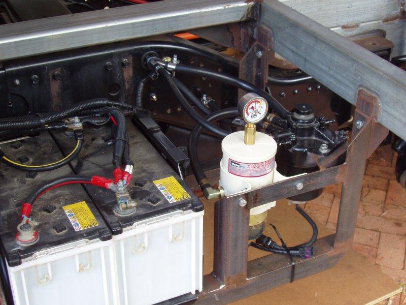
Moving the fuel tank between the chassis rails also meant that it was necessary to modify the original wiring harness for the fuel sender and fuel filter. The OEM fuel filter is now located on the opposite side of the truck, next to the main truck batteries. A dedicated water separator is also in the same location. A couple of extra brackets were made to mount these filters onto the existing battery bracket. There is plenty of room in this area for accessing both filters and the fuel primer.
Update – June 2012
As mentioned previously, I wanted to buy a new fuel sender for my tank, but couldn’t find one, so I was forced to modify the OEM sender.
I was never really happy with this setup, due to an oversight I made in my fuel tank design. The OEM fuel sender is a sweeping arm style, and because of this the float ends up being directly under the filler pipe when filling the tank. I should have placed the fuel sender on the opposite side of the tank, which would have negated this issue, but I didn’t. Hindsight is a wonderful thing…
One of the problems with finding an alternative fuel sender is that the OEM sender has a non standard hole pattern and ohm range.
A standard SAE 5 hole fuel sender pattern has a PCD of 54mm whereas the Fuso’s sender has a PCD of 58mm and an ohm range of zero when full and 150 ohms when empty. Unfortunately, there is no “off the shelf” fuel sender unit that matches the Fuso’s specifications.
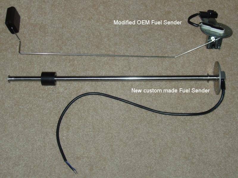
After much searching, and a bit of luck, I found a Chinese company that manufactures fuel senders, amongst other things. This company was willing to make a custom sender from the specifications I provided. Their fuel senders use a multitude of reed switches and permanent magnets in the float to vary the ohm range. Because the only moving part is the float, this style of sender is generally more robust than the sweeping arm style of sender. With this custom fuel sender fitted I am now 100% happy with my new fuel tank setup.
Dealing with Contaminated Fuel
Fuel contamination is a fact of life. For anyone that does not know, common rail diesel engines and water are mortal enemies.
Water can cause damage to injector components and reduce the lubricity of the fuel which in turn can cause seizure of close tolerance components, such as those found in fuel pump assemblies. Water in diesel will ultimately do damage to your injectors and injector pump, resulting in a very hefty repair bill. Basically, contaminated fuel can kill your engine!
It is impossible to guarantee the quality of your fuel, especially if you are filling up from from unfamiliar or remote locations. Having your vehicle die in the middle of nowhere due to bad fuel could prove expensive and potentially place you into a very dangerous situation.
For this reason, as part of the fuel tank upgrade I also decided to incorporate a high quality, dedicated water separator into the fuel system.
After considerable research, the unit I ended up buying was the Racor 500FG turbine series water separator/filter.
This filter uses a three stage process to cleanse the fuel:
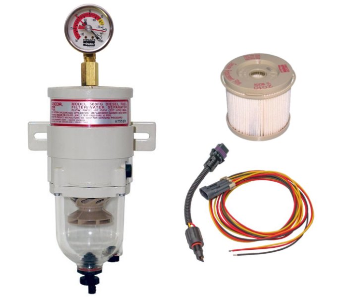
Stage One: Separation
As fuel enters the filter assembly, it moves through the centrifuge and spins off large solids and water droplets which fall to the bottom of the collection bowl.
Stage Two: Coalescing
Small water droplets bead-up on the surface of the conical baffle and cartridge element. When heavy enough, they too fall to the bottom of the bowl.
Stage Three: Filtration
Proprietary Aquabloc® cartridge elements repel water and can remove contaminants from fuel down to two micron (nominal).
These cartridges are waterproof and therefore remain effective longer than water absorbing elements.
The 500FG water separator is located between my new fuel tank and the OEM fuel filter.
One major factor to consider when using a second filter is that there cannot be much of an increase in restriction in the fuel pick-up line, as this can affect the functionality of the fuel pick-up pump. The primary function of the 500FG is water separation, not filtration, so a 30 micron filter (the largest available) will be used to minimise the restriction as much as possible. The 500FG has also been fitted with a vacuum gauge and a water in fuel (WIF) detection kit. The vacuum gauge helps monitor the filter condition, making it is easy to see if the filter is clean or dirty, and the water detection kit allows for a warning light to be mounted in the dash to indicate if water is present in the filter bowl, negating the need to physically monitor the filter bowl for water.
If the injector pump and injectors get damaged on the Fuso, the repair bill could exceed $15,000. ![]()
The Racor 500FG filter setup that I am using cost me about $350, which I think is a relatively cheap insurance policy against contaminated fuel.